


17
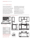
INSTALLATION I N ST RU C T IO N S
ELECTRICAL RE Q U I RE M E N TS
IMPORTANT NOTE:
Connection of this appli-
ance should be through a fused connection
unit or a suitable isolator, which complies with
national and local safety regulations. The
on/off switch should be easily accessible after
the appliance has been installed. If the switch
is not accessible after installation (depending
on country) an additional means of disconnec-
tion must be provided for all poles of the
power supply. When switched off there must
be an all pole contact gap of 3 mm in the
isolator switch. This 3 mm contact disconnect
gap must apply to any isolator switch, fuses
and/or relays according to EN60335.
The complete appliance must be properly
grounded at all times when electrical
p
ower is applied.
NOTE: Improper connection can result in
a fire hazard.
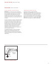
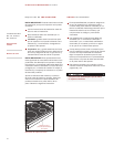
Before obtaining access to terminals, all
supply circuits must be disconnected.
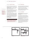
Open the terminal box to expose the screws
with corresponding numbers. Run the cord
through the strain relief hole and into the
terminal box.
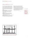
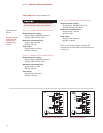
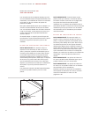
For Single Phase Install (Line, Neutral,
Ground):
Loosen the 1, 5, and ground screws.
Attach the Neutral wire to the number 5
position. Line should be attached to the 1
postion and attach the ground to the corre-
sponding ground screw.
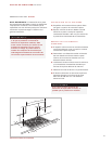
For 3phase Install (L1, L2, L3, Neutral,
Ground):
Loosen the 1, 2, 3 and remove the
copper bars. Loosen 5 and ground screws.
Attach L1 to position 1. L2 to position 2. L3 to
position 3. Neutral wire to position 5 and attach
the ground to the corresponding ground screw.
After tightening the screws, tighten down the
cord strain relief and close the cover to the
terminal box without pinching any of the wires.
Copper bars must be removed from posi-
tions 1, 2, and 3 when connecting to
3phase power.