


9
INSTALLATION INSTRUCTIONS
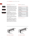
INSTALLATION SPECIFICATIONS
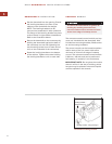
For installation of a downdraft system with a
cooktop, refer to the cooktop installation
instructions for the dimensions of the cooktop,
countertop cut-out and cabinet requirements.
The depth of the cooktop may vary and will
affect the location of the downdraft in the
countertop.
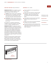
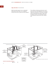
The illustration below provides countertop
cut-out dimensions for downdraft Models
ICBDD30, ICBDD36 and ICBDD45 installed with
a Wolf 762 mm or 914 mm cooktop or combi-
nation of cooktop and/or modules.
IMPORTANT NOTE:
For installation of a
downdraft with sealed burner rangetop
Models ICBSRT304 and ICBSRT366, an acces-
sory trim kit (810215) is necessary. Contact
your Wolf dealer for details. To obtain local
dealer information, visit our website, wolfap-
pliance.com.
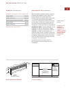
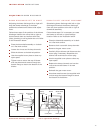
The control module can be positioned horizon-
tally or vertically and located anywhere within
3 m of the downdraft assembly and a
minimum of 76 mm from edge of cooktop cut-
out. Refer to page 11 for instructions to install
the control module.
IMPORTANT NOTE:
The downdraft must be
used with a Wolf-approved control module and
top cover.
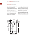
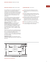
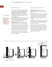
COUNTERTOP CUT-OUT
Layout and cut the cooktop cut-out far
enough forward so the downdraft will fit
behind it.
Set the cooktop in place and slide it as far
forward as possible. Center and square the
cooktop with edges of countertop.
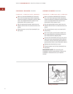
Place the plastic template included with the
downdraft against the back flange of the
cooktop and centered. Trace around the
template to mark the downdraft opening.
Remove the cooktop from countertop.
Cut the downdraft opening. Be careful not
to chip the edges of the countertop.
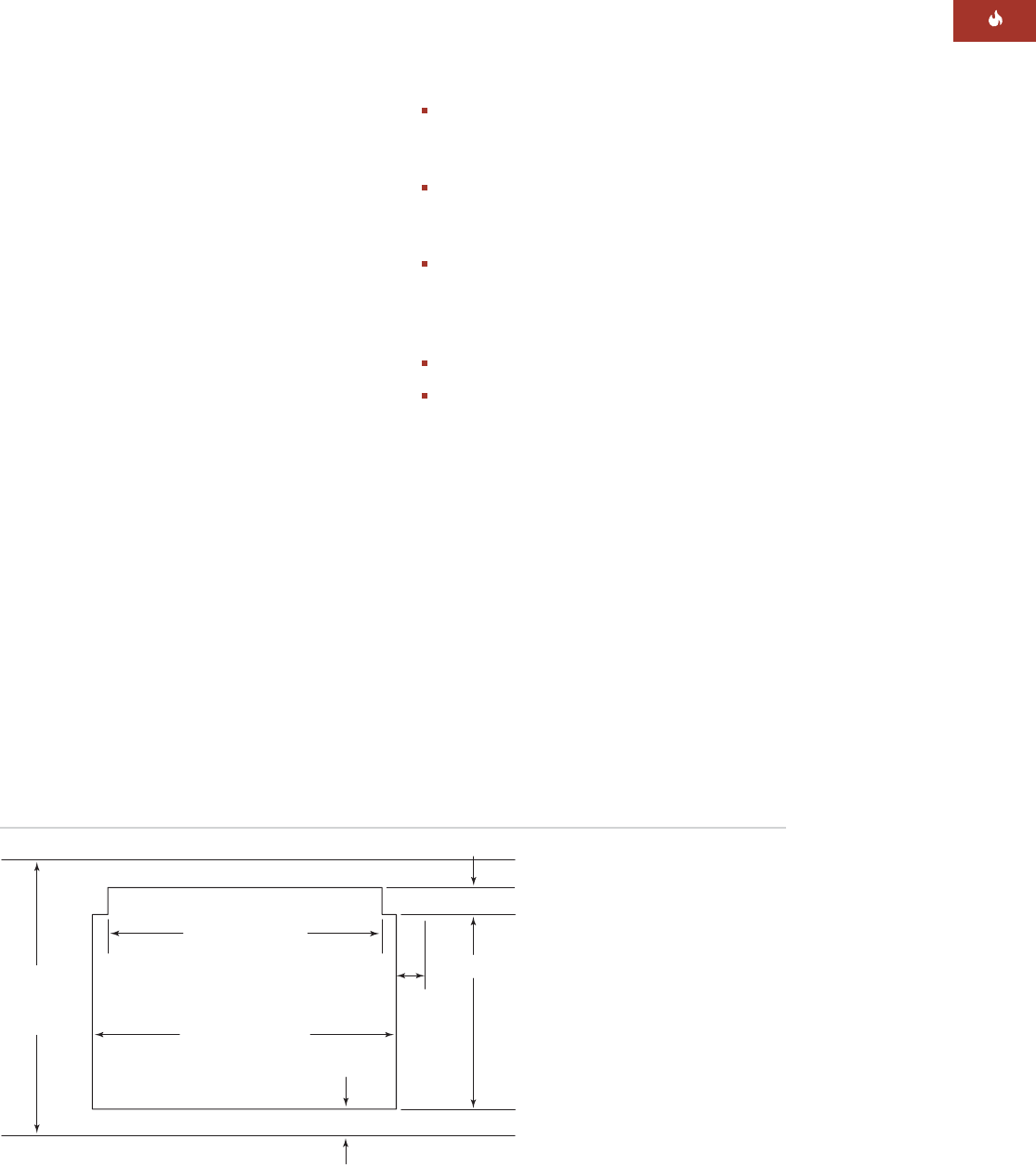
686 mm
FOR MODEL ICBDD30
838 mm
FOR MODEL ICBDD36
1067 mm
FOR MODEL ICBDD45
64 mm min
76 mm
min FOR
CONTROL
MODULE
COOKTOP CUT-OUT
WIDTH
638 mm min
FLAT
COUNTERTOP
SPACE
489 mm
70 mm
COUNTERTOP TOP VIEW
Countertop cut-out dimensions