FULL SIZE GAS CONVECTION OVENS - SERVICE PROCEDURES AND ADJUSTMENTS
F32700 (February 2006)Page 21 of 64
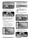
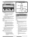
5. Reverse procedure to install.
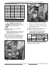
TEMP (°F) OHMS* TEMP (°F) OHMS*
77 90000 360 822
240 4077 380 656
260 3016 400 529
280 2266 425 424
300 1726 450 334
320 1332 475 266
340 1041
(*) Resistance in ohms ± 10%
GAS PRESSURE ADJUSTMENT
WARNING: DISCONNECT THE
ELECTRICAL POWER TO THE
MACHINE AND FOLLOW LOCKOUT /
TAGOUT PROCEDURES.
WARNING: SHUT OFF THE GAS BEFORE
SERVICING THE UNIT.
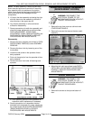
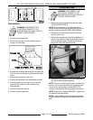
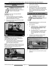
1. Remove the right side panel as outlined under
COVERS AND PANELS in REMOVAL AND
REPLACEMENT OF PARTS.
NOTE: If right side panel is not accessible, this
component can be serviced by removing the control
panel as outlined under COVERS AND PANELS.
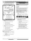
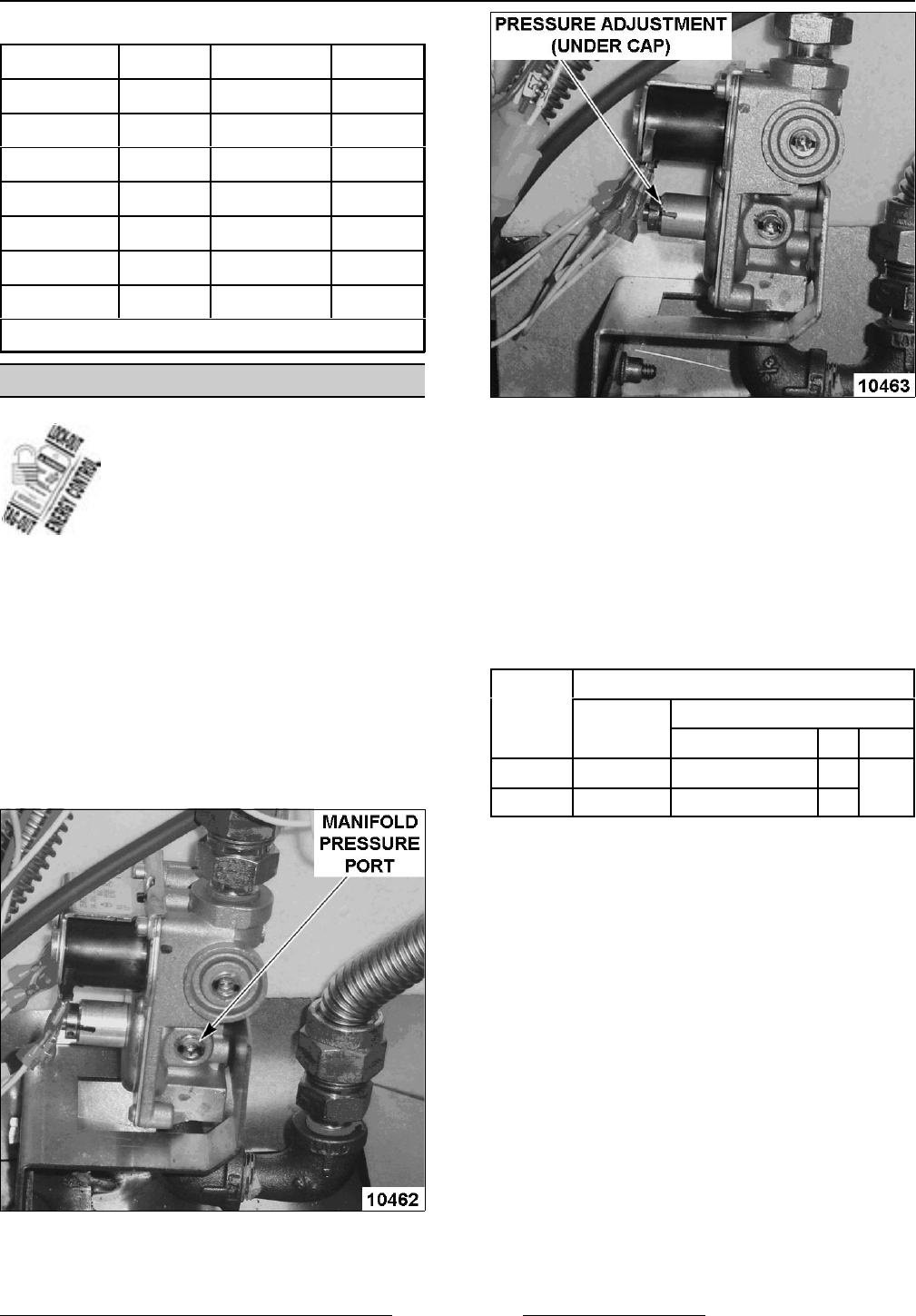
2. Remove the plug from the manifold pressure
port.
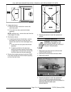
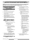
3. Install hose barb adapter and attach manometer
tube.
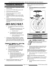
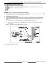
4. Remove adjustment screw cap from the gas
valve and turn gas supply to the oven back on.
5. Plug the unit in and turn the power switch ON.
6. Set the temperature control to its highest setting
and allow burner to ignite.
NOTE: Accurate gas pressure adjustments can only
be made with the gas on and the burner lit.
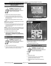
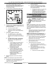
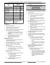
7. Turn the set screw to obtain the proper gas
pressure (clockwise = pressure increase;
counterclockwise = pressure decrease).
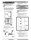
GAS
TYPE
PRESSURE READINGS (IN W.C.)
MANIFOLD
LINE
RECOMMENDED MIN MAX
Natural
3.5 7 5
14
Propane
10 11 11
NOTE: If the incoming line pressure to the valve is
less than the minimum stated, then the manifold
pressure can not be set correctly.


