


1
MICROMIX
Introduction
We at Yorkville Sound are confident that you will find your new MM4 to be an efficient
and versatile solution to your sound reinforcement needs. This manual contains informa-
tion to help you get the maximum performance from your Micromix. We hope you will
take the time to read it over.
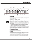
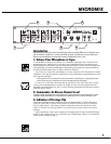
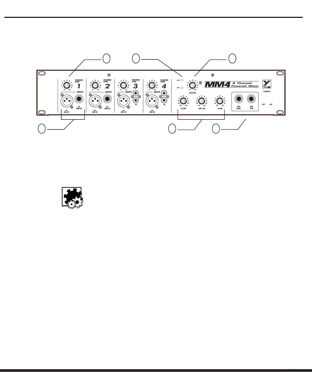
1. Microphone and Line Inputs
The MM4 features both balanced microphone and unbalanced line inputs on channels 1 and
2. The standard XLR type microphone inputs are electronically balanced for maximum noise
suppression. The input characteristics match those of professional low impedance dynamic
microphones such as the Shure® SM-58 and the Apex750.
The line inputs are standard 1/4-inch jacks which accept single-ended signals from
guitars, synthesizers, electric pianos, tape recorders, unbalance high-impedance micro-
phones, and the like.
Do not connect signals to both types of inputs on any one channel. Use either the
unbalanced or the balanced input on any one channel, but not both. Connecting to both
inputs on one channel will cause improper operation of the input circuit.
Channel 3 and 4 are special channels, in which the line inputs (1/4-inch jack) have
been replaced by two RCA jacks. The XLR balanced input functions identically to the other
XLR inputs, but the RCA inputs are specifically intended to receive stereo signals from
compact disk players or tape players. Within the MM4, these stereo signals are electroni-
cally summed to a mono signal.
2. Channel Level Controls
Each channel has a separate level control. Advancing this control increases the contribution
of the associated channel’s signal to the overall mix.
3. Clip LED
The Clip LED is located next to the master control. It will light when any signal anywhere
within the mixer section gets to within 3 dB of clipping. Under normal use, it is expected
that this LED will flash for brief instants during the loudest musical peaks. If the clip LED is
off, you can be sure that the mixer section of the MM4 is not clipping.
The LED circuitry is intended to indicate clipping only in the mixer section of the MM4.
It is not implemented as an indicator of clipping in the power-amp section. Remember also
that the clip LED can’t indicate clipping in any external amplifier connected to the MM4.
UNBAL
CD/TAPE
LINE IN
UNBAL
CD/TAPE
LINE IN
5
6
3
2 4
1