


3
Master Section
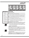
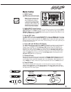
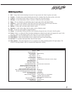
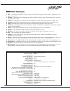
1. MAIN Control
The MAIN control adjusts the overall
level of the main mix, the PA volume.
Note: To ensure maximum sig-
nal headroom and clarity, first
set the MAIN level control to
7, then set the channel LEVEL
controls for a good signal with-
out clipping, then go back to the
MAIN level control and adjust
for the overall volume desired.
2. MAIN EFFECTS Level Control
The MAIN EFX control adjusts the amount of signal from the output of the internal Digital
Effects Processor to the MAIN mixing bus where it is mixed with the audio signal from the
CHANNEL LEVEL controls. The MAIN EFX control adjusts the intensity of the effects on the
left and right MAIN output signals.
3. Record OUT Jacks
The Record OUT audio signal at the Record OUT RCA jacks is the MAIN audio signal from
channels 1 to 5, but without DIGITAL EFFECTS, and pre-GRAPHIC EQUALIZER. The Record
OUT level control, located to the left of the MAIN control, adjusts the audio signal level
going to these jacks. Using RCA patch cords, connect directly to the inputs (line-level) of
an audio recording device.
4. Power LED and VU-Meter LED Display
The Power LED lets you know that the MM5D is plugged in, turned on and all systems
are normal. The VU-Meter LEDs indicate the level of the audio signal going to the
internal power amplifiers. The 0dB VU-Meter LED indicates when the amplifiers are
delivering full power. Because there is an audio limiter on the input of each power
amplifier, you can turn up the MAIN level control until the VU-Meter Clip LED illumi-
nates where the audio limiter is at maximum compression. For maximum audio power
output the MM5D sounds the best if the +3dB VU-Meter LED is illuminated but the
VU-Meter Clip LED does not illuminate.
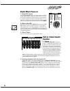
5. Phantom Power
Regular dynamic microphones can be used with the Phantom Powered XLR Channel inputs.
Connecting a dynamic or condenser microphone to the MM5D when the MM5D’s power is
on will create a loud, potentially damaging pop in the loudspeakers. When setting up, turn
off the MM5D’s AC power, connect all of your microphones then turn the MM5D power on.
6. Tape/CD Input
There are left and right RCA inputs jacks on the front panel to connect a CD player,
cassette player, MP3 player, or other stereo source to the mixer. These inputs connect
directly to the MAIN bus, and to the Record OUT bus. The Tape/CD level control adjusts
the input level of the audio signal.
0
5
28
7
6
4
3
91
10
0
5
28
7
6
4
3
91
10
0
5
28
7
6
4
3
91
10
0
5
2 8
7
6
4
3
91
10
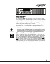
+15
+10
+5
0
-5
-10
-15
100 250 500 1.0K 2.0K 5.0K 10.0K
Clip
0 dB
+3
-6
-12
Tape/CD In
Record Out
Level
EFX Level
Power
EFX
clip
Hall
Chamber
Lg Room
Sm Room
Stage
Ambience
Arena
Stadium
1.
2.
3.
4.
5.
6.
7.
8.
9.
10.
11.
12.
13.
14.
15.
16.
Slap Back
Echo
Flanger
Chorus
Chorus Room 1
Chorus Room 2
Dry Vocal
Rotary Speaker
1
2
3
4
5
6
7
8
9
1 0
1 1
1 2
1 3
1 4
1 5
1 6
VU Meter
Record OUTTape/CD In
EQUALIZEREffects
2 x 90 Wa tt Mixer
with 24-Volt
Phantom Power
VU Meter
EQUALIZEREffects
VU Meter
MAIN
EQUALIZEREffects
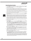
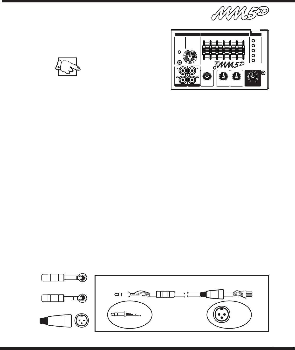
1/4-inch T.R.S.
Phone Plug
Balanced 1/4-inch T.R.S. to Balanced XLR
XLR Plug
(Male)
Tip = 0°
Ring = 180°
Sleeve = Ground
1
Pin 1 = Ground
Pin 2 = 0°
Pin 3 = 180°
2
3
1/4-inch Phone Plug
1/4-inch T.R.S. Phone Plug
XLR Plug