


GAS CONNECTION
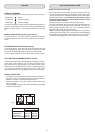
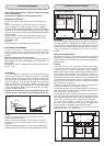
The cooker is fitted with 4 legs for an eventual alignment in height
with the furniture. To assemble them, it is necessary to raise the
cooker and to screw the four legs into the suitable threadings
placed on the corners on the bottom of the appliance.
Fig. 12
This appliance must be installed in accordance with the Gas Safety
(Installation and Use) Regulations (current edition) and the I.E.E
Wiring Regulations.
Detailed recommendations are contained in the following British
Standard Codes of Practice - B.S 6172, B.S 5440: Part 2 and B.S.
6891: Current Editions
For appliances installed in the Republic of Ireland please refer to
NSAI- Domestic Gas Installation I.S 813 Current Editions and the
ETCI Rules for Electrical Installations.
IMPORTANT
This cooker is supplied for use on Natural Gas Only and cannot
be used for any other gas without modification.
Conversion for use on LPG and other gases must only be
undertaken by a qualified person. For information for use on other
gases contact your local Service Centre.
The cooker must be installed by a qualified person in accordance
with the Gas Safety (Installation and Use) (Amendment) Regulations
1990 and the relevant building/I.E.E. Regulations.
Failure to install the appliance correctly could invalidate any
manufacturers warranty and lead to prosecution under the above
quoted regulations.
In the UK, CORGI registered installers are authorised to undertake
the installation and service work in compliance with the above
regulations.
Provision for Ventilation
The room containing the cooker should have an air supply in
accordance with BS 5440: Part 2: The room must have an opening
windows or equivalent; some rooms may also require a permanent
vent. If the room has a volume between 5 and 10m
3
, it will require
an air vent of 50cm
2
effective area unless it has a door which
opens directly to the outside. If the room has a volume of less
than 5m
3
, it will require an air vent of 100cm
2
effective area. If
there are other fuel burning appliances in the same room, BS
5440: Part 2: 1989 should be consulted to determine air vent
requirements. Ensure that the room containing the cooker is well
ventilated, keep natural ventilation holes or install a mechanical
ventilation device (mechanical cooker hood). Prolonged intensive
use of the appliance may call for additional ventilation, for example
opening of a window, or more effective ventilation, for example
increasing the level of mechanical ventilation where present. This
cooker is not fitted with a device for discharging the products of
combustion. Ensure that the ventilation rules and regulations are
followed. Excess steam from the oven, vents out at the top back
edge of the cooker, so make sure that the walls behind and near
the cooker are resistant to heat, steam and condensation. Your
cooker must stand on a flat surface so that when it is in position
the hob is level. When in position check that the cooker is level
by using a spirit level and adjust the 2 feet at the rear and the 2
feet at the front if necessary. It is important that the cooker is
stable and level for the overall cooking performance.
Remember that the quantity of air necessary for combustion must
never be less than 2m
3
/h for each kW of power (see total power
in kW on the appliance data plate).
Gas Safety (Installation & Use) Regulations
It is the law that all gas appliances are installed by competent
persons in accordance with the current edition of the Installation
& Use Regulations. It is in your interest and that of safety to
ensure compliance with the law.
In the UK, CORGI registered installers work to safe standards of
practice. The cooker must also be installed in accordance with
the current edition of BS 6172. Failure to install the cooker correctly
could invalidate the warranty, liability claims and could lead to
prosecution.
Gas Connection (all installation and service work must be
carried by a CORGI registered engineer)
Prior to installation, ensure that the local distribution conditions
(nature of the gas and gas pressure) and the adjustment conditions
are compatible. The adjustment conditions for this appliance are
stated on the rating plate, located on the inside the front appliance
drawer.
This appliance is not designed to be connected to a combustion
products evacuation device. Particular attention should be given
to the relevant requirements regarding ventilation.
Connection to the cooker should be made with an approved
appliance flexible connection to BS 669. Models for use with LPG
should be fitted with a hose suitable for LPG and capable of
withstanding 50mbar pressure. A length of 0.9 to 1.25m is
recommended. The length of hose chosen should be such that
when the cooker is in situ, the hose does not touch the floor.
The temperature rise of areas at the rear of the cooker that are
likely to come in contact with the flexible hose do not exceed
70
0
C.
Gas pressure may be checked on a semi-rapid hob burner. Remove
the appropriate injector and attach a test nipple. Light the other
burners and observe that the gas pressure complies with the gas
standards in force.
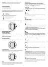
Certain types of cookers can be connected to the supply both on
the right and left hand side at the rear of the cooker. To reverse
the position, remove the blanking plug and refit in the side not to
be used. On completion carry out a gas soundness.
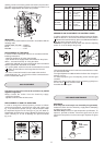
ELECTRICAL CONNECTION
OK NO
Fig. 13
INLETSTOP
This appliance must be installed by a qualified person in
accordance with the latest edition of the IEE Regulations and
in compliance with the manufacturer instructions.
Ensure that the voltage is the same as that stated on the rating
plate. The rating plate can be found on the back cover of this
book.
WARNING! THIS APPLIANCE MUST BE EARTHED
The cooker must be connected to a suitable cooker control unit
incorporating a double pole switch having a contact separation
of at least 3mm in all poles, which is adjacent to (but not above),
and not more than1.25m away from the cooker and easily
accessible. We recommend that the cooker circuit is rated to
20amps.
Cable type H05 RRF 3X 2.5mm2
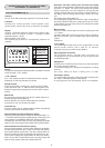
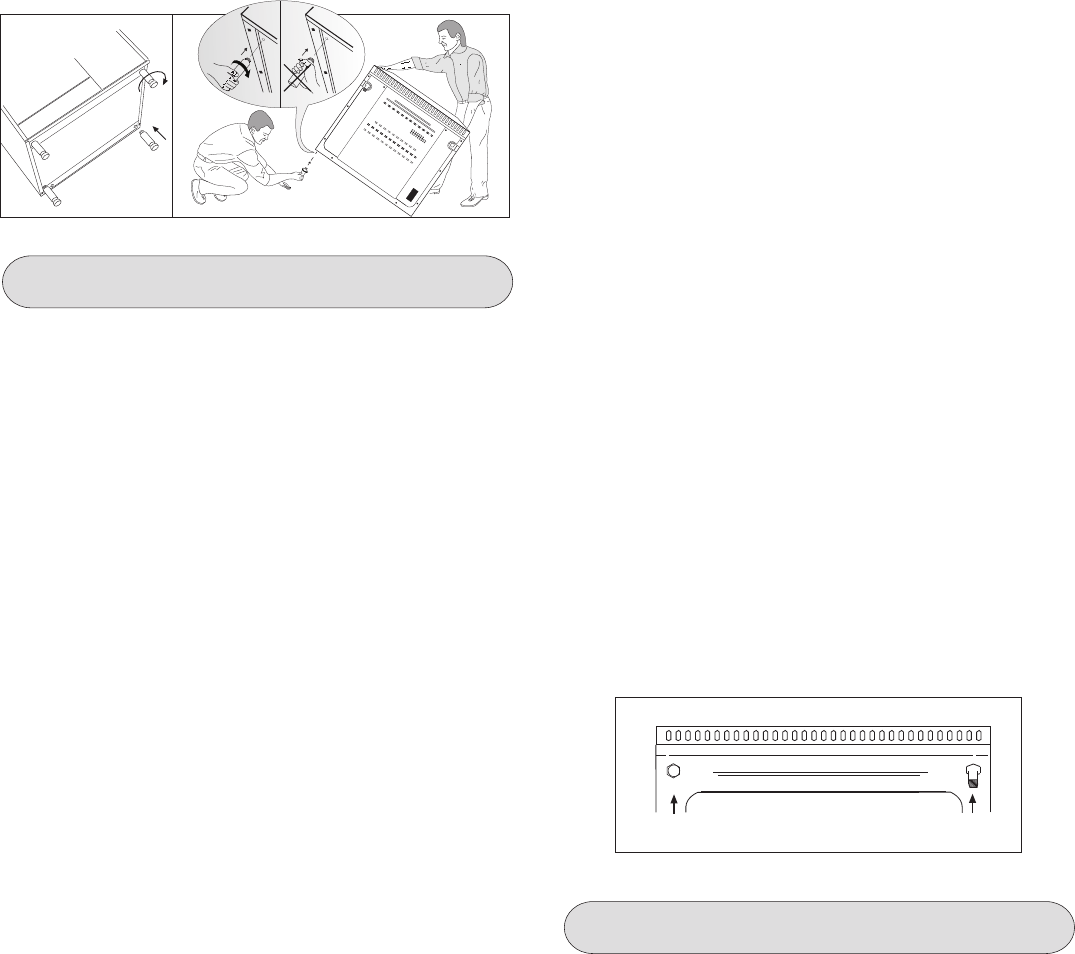
Connecting the mains cable
Open the mains terminal block cover as shown over, unscrew the
cableclamp «A» and unscrew (not fully) the screws in the mains
terminal
block «L N E» which secure the three wires of the mains
cable.Fit the cable and refit the cable clamp «A» .
Allow sufficient cable length for the cooker to be pulled out for
10