


GAS ADJUSTMENT
APPLIANCE MAINTENANCE
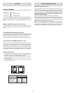
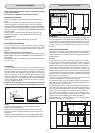
E 14
25 W - 230 V~
T300°C
A
2
1
3
4
5
L
N
A
IMPORTANT
The wires in the mains lead are coloured in accordance with the
following code:
GREEN AND YELLOW .....EARTH
BLUE .................................NEUTRAL
BROWN.............................LIVE
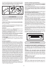
REPLACEMENT OF THE CABLE
In case the cable is damaged, replace it in accordance with the
following instructions:
- switch the appliance off at the control switch
- open the box of the supply board as described on the picture
above; - unscrew the clamp «A» fixing the cable;
- replace the cable with one of the same length and in accordance
with the specification described on the table;
- the “green-yellow” earth wire must be connected to the terminal
“ ” and it must be about 10 mm longer than the live and
neutral wires;
- the «blue» neutral wire must be connected to the terminal
marked with letter «N.» - the live wire must be connected to the
terminal marked with letter «L».
Conversion to LPG (all work must be carried out by CORGI
registered engineers)
Always isolate the cooker from the electricity supply,
- change the injectors,
- adjust the minimum flow of the burners.
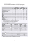
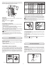
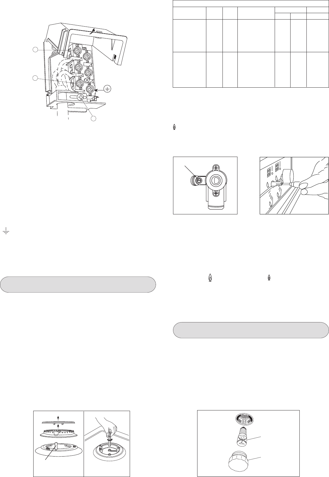
REPLACEMENT OF HOB-TOP INJECTORS
In order to change the hob-top injectors, procees as follows:
remove the panstands, remove burner caps and crowns (see
fig. 14 A) unscrew the injector (see fig. 14 B) and replace it with
the stipulated injector for the new type of gas (see table D).
Reassemble all of the burners, paying attention to place the burner
crown carefully so as not to damage the spark electrode
(fig.14 A).
Fig. 14
A B
TAB. D GENERAL INJECTORS TABLE
Kind of gas mbar Nozzle Burners Power Watt Consum.
N. Posizione-type max. min. max.
1.15 -Rapide 3000 750 286 l/h
NATURAL 20 0.97 -Semi rapide 1750 480 167 l/h
0.72 -Auxiliary 1000 330 95 l/h
1.28 -Triple crown 3300 1300 315 l/h
G.P.L. 30 0.85 -Rapide 3000 750 219 g/h
BUTANE 28 0.65 -Semi rapide 1750 480 128 g/h
PROPANE 37 0.50 -Auxiliary 1000 330 73 g/h
0.93 -Triple crown 3300 1300 241 g/h
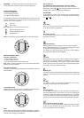
MINIMUM FLOW ADJUSTMENT FOR CONTROL KNOBS
In order to adjust the minimum flame setting proceed as follows:
switch the burner on, and set the knob at the minimum position
. Remove the knob from the tap, place a small bladed screwdriver
down the centre of the tap shaft (fig. 15).
Attention: on taps with a security valve, the minimum adjusting
screw «Z» is on the body of the gas tap.
Unscrew the adjusting screw in order to increase the flow or screw
it to decrease the flow.
The right adjustment is obtained when the flame has a length of
about 3 or 4 mm.
For butane/propane gas, the adjusting screw must be tight
screwed.
Make sure that the flame does not go out passing quickly from
the max. flow to the minimum flow .
Assemble the knob again.
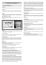
WARNINGS
Oven lamp (the oven lamp is not covered by the guarantee)
Isolate the cooker from the electricity supply before attempting
to replace the oven lamp.
The oven lamp used has a high temperature specification. To
replace it, proceed as follows: remove the glass cover (A) and
replace the lamp with one of the same type. Replace the glass
cover.
Fig. 17
cleaning, but do not let it hang closer than 50mm (2") to the floor.
The cable can be looped if necessary, but make sure that it is not
twisted or trapped when the cooker is in position.
Z
Fig. 15 Fig. 16
electrode
11