


30
INSTALLATION
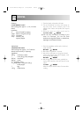
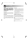
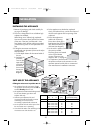
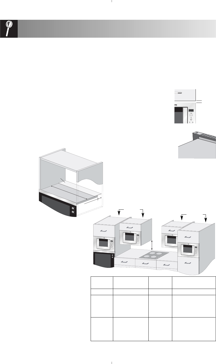
If fitting the microwave in position B or C:
• The cupboard must be a minimum of 500
mm (E) above the worktop and must not be
installed directly above a hob.
• This appliance has been tested and approved
for use near domestic gas, electric and
induction hobs only.
• Sufficient space between hob and
microwave should be allowed to prevent
overheating of microwave oven,
surrounding cupboard and accessories.
• Do not operate the hob without pans when
the microwave oven is operating.
• Care should be taken when attending to the
microwave oven while the hob is on.
E
D
SAFE USE OF THE APPLIANCE
INSTALLING THE APPLIANCE
1. Remove all packaging and check carefully for
any signs of damage.
2. This oven is designed to fit into a 360mm high
cupboard as standard.
When fitting into a 350mm high cupboard:-
Unscrew and remove the 4 feet from the bottom
of the oven. There are 3 tall feet and 1 short
foot. Replace the 3 tall feet with those provided
in the accessory pack. Do not replace the short
foot.
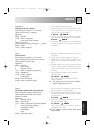
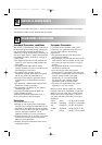
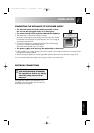
3. If fitting the microwave oven above a
conventional oven (position A) then use the mylar
sheet provided.
a. Cut the Mylar sheet to fit the internal width of
the unit.
b. Peel back the
protective
cover on the
tape and fix
to the rear of
the shelf so
that it covers
the service
gap. (See
diagram).
4. Fit the appliance into the kitchen cupboard
slowly, and without force, until the front frame of
the oven seals against the front opening of the
cupboard.
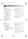
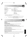
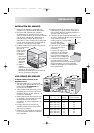
5. Ensure the appliance is
stable and not leaning.
Ensure that a 5mm gap is
kept between the cupboard
door above and the top of
the frame (see diagram).
6. Fix the oven in position with
the screws provided.
The fixing points are located
on the top and bottom
corners of the oven (see
diagram, item 9, on page 4).
7. It is important to ensure that the installation of
this product conforms to the instructions in this
operation manual and the hob or conventional
oven manufacturer’s installation instructions.
5 mm
Position A
Position B
Position C
Position D
Conventional
oven
Mylar sheet
Conventional
oven
Internal width
Service gap
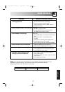
POSITION NICHE SIZE CHIMNEY Gap Between
WD H (min) Cupboard & Ceiling
A 560 x 550 x 360 50 50
B + C 460 x 300 x 350 18 50
460 x 300 x 360 18 50
560 x 300 x 350 18 50
560 x 300 x 360 18 50
D 460 x 500 x 350 18 50
460 x 500 x 360 18 50
560 x 500 x 350 18 50
560 x 500 x 360 18 50
Measurements in (mm)
Chimney
Chimney
1. ZD-21+22D-EU English 01/06/2004 08:42 Page 30