Auto Detect Implementation in VLAN Interface Backup 537
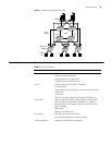
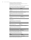
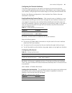
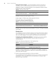
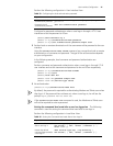
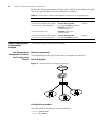
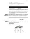
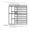
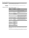
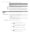
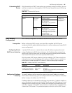
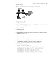
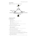
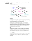
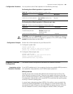
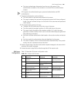
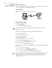
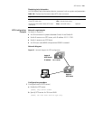
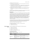
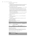
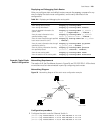
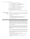
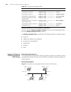
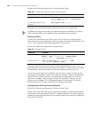
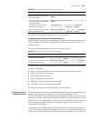
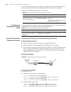
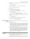
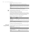
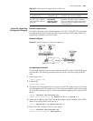
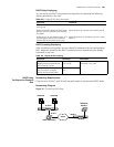
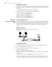
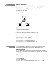
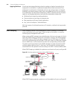
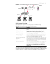
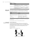
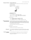
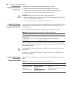
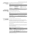
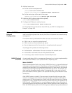
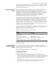
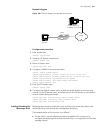
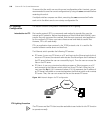
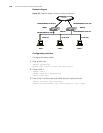
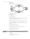
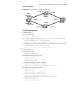
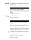
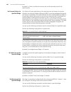
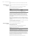
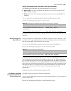
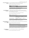
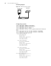
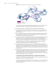
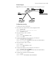
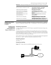
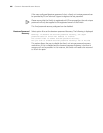
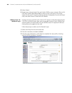
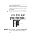
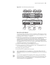
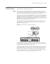
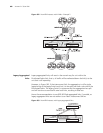
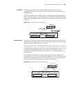
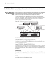
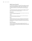
Network diagram
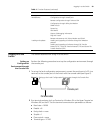
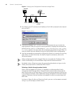
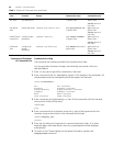
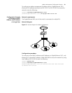
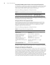
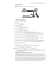
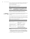
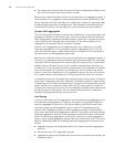
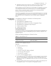
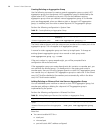
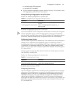
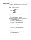
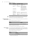
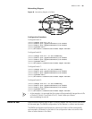
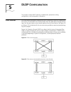
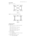
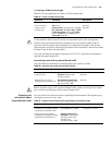
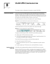
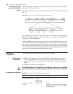
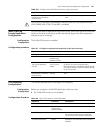
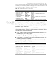
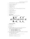
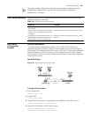
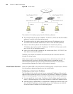
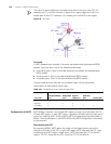
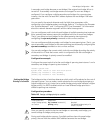
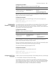
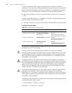
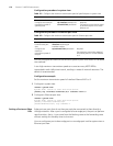
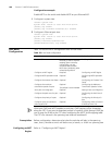
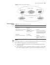
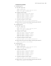
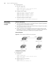
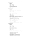
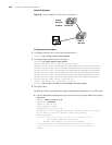
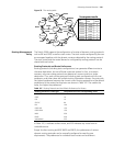
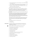
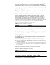
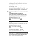
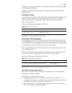
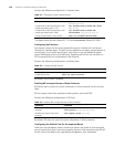
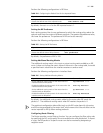
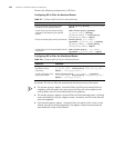
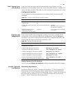
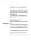
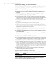
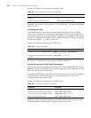
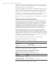
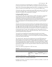
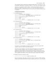
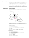
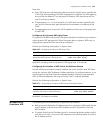
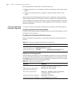
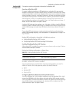
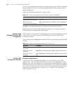
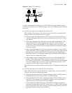
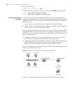
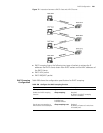
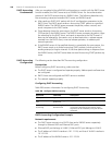
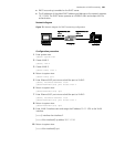
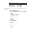
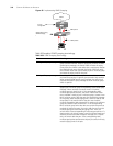
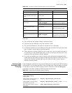
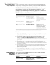
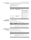
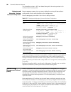
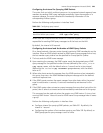
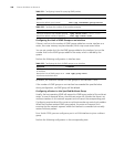
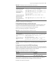
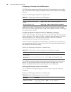
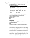
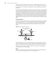
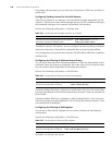
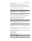
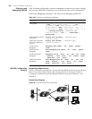
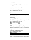
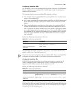
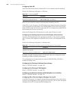
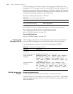
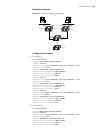
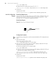
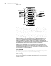
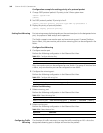
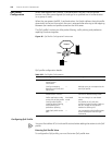
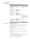
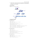
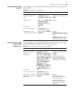
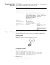
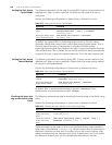
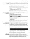
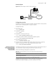
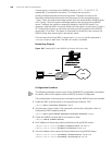
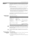
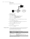
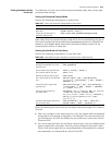
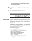
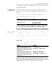
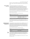
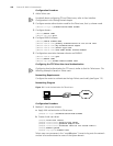
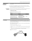
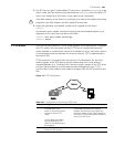
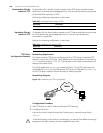
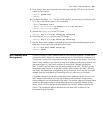
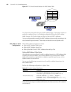
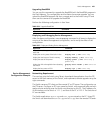
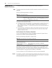
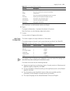
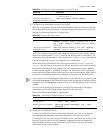
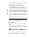
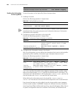
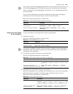
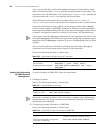
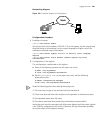
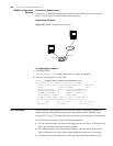
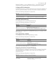
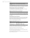
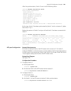
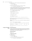
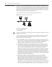
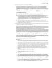
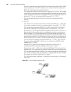
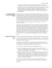
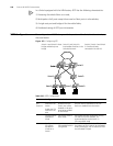
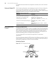
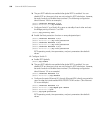
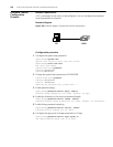
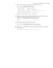
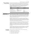
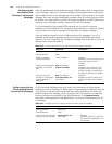
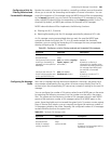
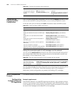
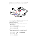
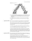
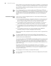
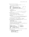
Figure 158 Network diagram for VLAN interface backup
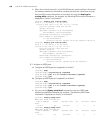
Configuration procedure
1 Configure Switch C.
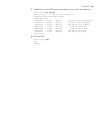
a Enter system view.
<S5500 C> system-view
b Configure a static route to VLAN interface 1 on Switch A as the primary route,
with the IP address of 10.1.1.3 as the next hop.
[S5500 C] ip route-static 192.168.1.1 24 10.1.1.3
c Configure a static route to VLAN interface 2 on Switch A as the secondary route,
with the IP address of 20.1.1.3 as the next hop.
[S5500 C] ip route-static 192.168.2.1 24 20.1.1.3
2 Configure Switch A.
a Enter system view.
<S5500 A> system-view
b Add Ethernet1/0/1 port to VLAN 1.
[S5500 A] vlan 1
[S5500 A-vlan1] port ethernet1/0/1
[S5500 A-vlan1] quit
c Assign an IP address to VLAN 1 interface.
[S5500 A] interface vlan-interface 1
[S5500 A-vlan-interface1] ip address 192.168.1.1 24
d Add Ethernet1/0/2 port to VLAN 2.
[S5500 A] vlan 2
[S5500 A-vlan2] port ethernet1/0/2
e Assign an IP address to VLAN 2 interface.
[S5500 A] interface vlan-interface 2
[S5500 A-vlan-interface2] ip address 192.168.2.1 24
f Create detecting group 10.
[S5500 A] detect-group 10
192.168.1.1
192.168.2.1
192.168.1.2
192.168.2.2 20.1.1.2
10.1.1.3
Ethernet 1/0/1
Ethernet 2/0/1
Switch A
Switch B
Switch C
Switch D
192.168.1.1/24
192.168.2.1/24
192.168.1.2/24
192.168.2.2/24 20.1.1.2/24
10.1.1.3/24
10.1.1.4/24
Switch A
Switch B
Switch C
Switch D
VLAN 1
VLAN 2
192.168.1.1
192.168.2.1
192.168.1.2
192.168.2.2 20.1.1.2
10.1.1.3
Ethernet 1/0/1
Ethernet 2/0/1
Switch A
Switch B
Switch C
Switch D
192.168.1.1/24
192.168.2.1/24
192.168.1.2/24
192.168.2.2/24 20.1.1.2/24
10.1.1.3/24
Ethernet 1/0/1
Ethernet 1/0/2
Switch A
Switch B
Switch C
Switch D
VLAN 1
VLAN 2
20.1.1.4/24