Specifications are subject to change without notice
AtlasSound.com
1601 JACK MCKAY BOULEVARD ENNIS, TEXAS 75119 U.S.A. • TELEPHONE: (800) 876-3333 • FAX: (800) 765-3435
©2005 ATLAS SOUND LP Printed in U.S.A. ATS002102 RevC 9/05 PP
OWNER'S MANUAL
CP700 COMMERCIAL
POWER AMPLIFIER
4
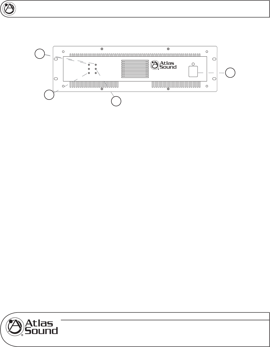
FRONT PANEL DESCRIPTION
Figure 1
1. Power Switch
This rocker switch supplies power to the CP700 amplifi er. A red LED located above the power switch
will illuminate when the CP700 is switched on.
2. Protect LED Indicators
The CP700 features several types of protection circuitry to prevent damage during turn-on or fault
conditions. If any of these LEDs illuminate, one of the various protection features is safeguarding the
amplifi er. The output relays will disconnect the speaker loads when the protection circuitry detects a
fault condition.
• Loudspeaker Protection - When power is fi rst applied, the speaker protection relay is
open, preventing transients from reaching the loudspeakers. After the internal power supplies
have stabilized, the relay will close, connecting the amplifi er output to the load. The yellow
Protect LEDs will illuminate during this power up process.
• Thermal Protection - The CP700 protection circuitry monitors itself for excessive internal
operating temperatures. In the event of this circuitry detecting abnormal thermal conditions
(blocked cooling fan and high ambient temperatures), the speaker relay will disconnect the
speaker load from the amplifi er. Once the internal operating temperature drops back to a safe
level, the relay will close, reconnecting the speaker load to the amplifi er.
• Short Circuit Protection - The yellow Protect LEDs will illuminate should the amplifi er detect
a short circuit on the attached speaker load or if the load impedance is too low. When this
condition is detected, the internal speaker relays will open up, disconnecting the load from
the amplifi er. The protection circuitry will stay activated until the fault is cleared.
Note: Once the specifi c fault has been corrected, the power may have to be cycled to reset the
protection circuitry.
3. Signal "Status" LED Indicator
The green "Status" LEDs will illuminate once the input signal has reached -26dBv or higher.
PROTECT
LIMIT
SIGNAL
CH-1
PROTECT
POWER
LIMIT
SIGNAL
CH-2
CP700
Commercial Power Amplifier
2
3
4
1


