3
DesIgn specIfIcatIons
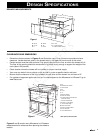
• Dimensions that are shown in Figures 2 and 3 must be used. Given dimensions provide minimum
clearance. Locate electrical outlet in the shaded area in the upper left-hand corner of the cutout.
• Contact surface must be solid and level. Pay special attention to the floor on which the drawer will sit.
The floor of the opening should be constructed of plywood strong enough to support the weight of the
oven (about 100 pounds).
• Check
location where the drawer will be installed for proper electrical supply.
• Your oven can be built into a cabinet or wall by itself or under a specific electric wall oven.
• Be sure that the clearance of the floor between the wall oven and the drawer is a minimum of 2".
• For updates of approved appliances that can be used adjacent to the Microwave In-A-Drawer™ go to
www.Dacor.com.
DRAWER MEASUREMENTS
Figures 2 and 3 contain many Microwave In-A-Drawer™
measurements for reference when planning the drawer’s
location.
CLEARANCES AND DIMENSIONS
NOTE:OpenTop Cabinet illustrated
A. 6"
B. Electrical outletlocation
C. Anti-Tip block
D. 5"
E. 3 1/2"
F. 4"
G. 28 7/16"opening
K. Allow 1/4"overlap
H. 14 3/4"to bottom of Anti-Tipblock
I. Allow 3/4"overlap
J. 23 1/2"minimum depth
Q. 15 3/16"± 1/16" opening
L. 36" countertopheight
M. Allow 7/16"overlap
N. Floor mustsupport 100 lbs.
O. 19" totop of floor
P. *30" cabinetminimum
A
B
C
D
E
F
G
H
I
I
J
K
L
M
N
O
P
Q
A
B
C
F
I
D
H
G
E
A
B
C
L
K
J
D
E
G
H
F
I
M
M
N
O
P
Q
R
S
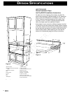
A. 28 1/8"
B. 4 11/16"
C. 2"
G. 15 1/16"
H. 1 1/4" doorthickness
I. 13 5/8" autodrawer opening
D. 23 3/8"
E. 30"
F. 15 5/8"
A. 84"wall cabinet
B. Optionalwall oven cutoutillustrated in
sketch
C. Electricaloutlet location
D. 6"
E. Anti-Tipblock
F. 31/2"
G. 5"
H. 4"
I. 2"minimum
J. 287/16" opening
K. Allow1/4" overlap
L. 143/4" to bottomof Anti-Tip block
M. Allow3/4" overlap
N. 231/2" minimum depth
O. 153/16" ± 1/16"opening
P. Allow7/16" overlap
Q. Floormust support 100lbs.
R. *19" to topof floor (recommended)
S. 30"cabinet minimum
Figure 1
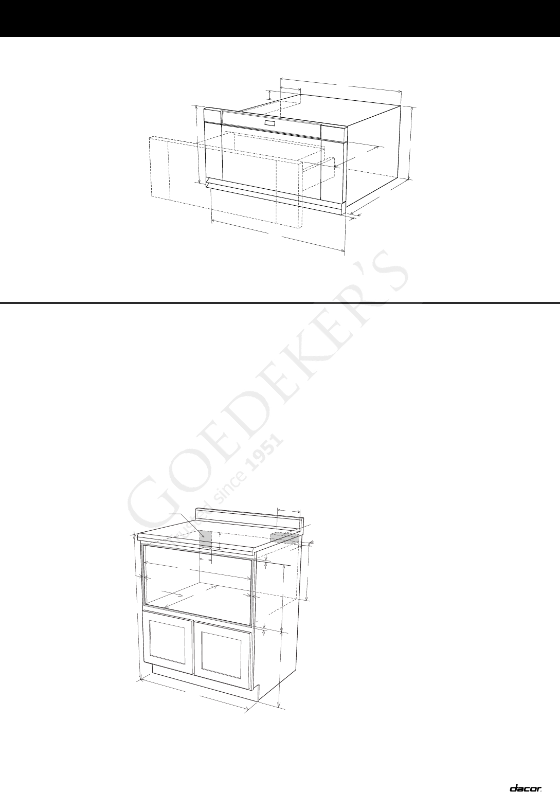
Figure 3 Figure 2
Figure 1
NOTE:OpenTop Cabinet illustrated
A. 6"
B. Electrical outletlocation
C. Anti-Tip block
D. 5"
E. 3 1/2"
F. 4"
G. 28 7/16"opening
K. Allow 1/4"overlap
H. 14 3/4"to bottom of Anti-Tipblock
I. Allow 3/4"overlap
J. 23 1/2"minimum depth
Q. 15 3/16"± 1/16" opening
L. 36" countertopheight
M. Allow 7/16"overlap
N. Floor mustsupport 100 lbs.
O. 19" totop of floor
P. *30" cabinetminimum
A
B
C
D
E
F
G
H
I
I
J
K
L
M
N
O
P
Q
A
B
C
F
I
D
H
G
E
A
B
C
L
K
J
D
E
G
H
F
I
M
M
N
O
P
Q
R
S
A. 28 1/8"
B. 4 11/16"
C. 2"
G. 15 1/16"
H. 1 1/4" doorthickness
I. 13 5/8" autodrawer opening
D. 23 3/8"
E. 30"
F. 15 5/8"
A. 84"wall cabinet
B. Optionalwall oven cutoutillustrated in
sketch
C. Electricaloutlet location
D. 6"
E. Anti-Tipblock
F. 31/2"
G. 5"
H. 4"
I. 2"minimum
J. 287/16" opening
K. Allow1/4" overlap
L. 143/4" to bottomof Anti-Tip block
M. Allow3/4" overlap
N. 231/2" minimum depth
O. 153/16" ± 1/16"opening
P. Allow7/16" overlap
Q. Floormust support 100lbs.
R. *19" to topof floor (recommended)
S. 30"cabinet minimum
Figure 1
Figure 3 Figure 2
Figure 2