4
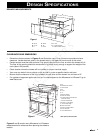
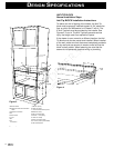
NOTE:OpenTop Cabinet illustrated
A. 6"
B. Electrical outletlocation
C. Anti-Tip block
D. 5"
E. 3 1/2"
F. 4"
G. 28 7/16"opening
K. Allow 1/4"overlap
H. 14 3/4"to bottom of Anti-Tipblock
I. Allow 3/4"overlap
J. 23 1/2"minimum depth
Q. 15 3/16"± 1/16" opening
L. 36" countertopheight
M. Allow 7/16"overlap
N. Floor mustsupport 100 lbs.
O. 19" totop of floor
P. *30" cabinetminimum
A
B
C
D
E
F
G
H
I
I
J
K
L
M
N
O
P
Q
A
B
C
F
I
D
H
G
E
A
B
C
L
K
J
D
E
G
H
F
I
M
M
N
O
P
Q
R
S
A. 28 1/8"
B. 4 11/16"
C. 2"
G. 15 1/16"
H. 1 1/4" doorthickness
I. 13 5/8" autodrawer opening
D. 23 3/8"
E. 30"
F. 15 5/8"
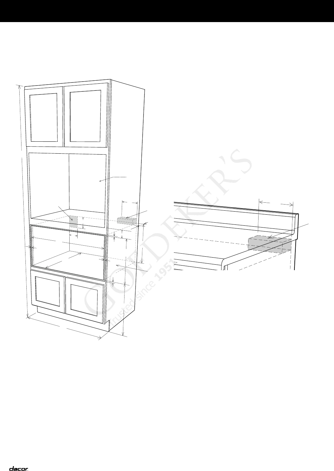
A. 84"wall cabinet
B. Optionalwall oven cutoutillustrated in
sketch
C. Electricaloutlet location
D. 6"
E. Anti-Tipblock
F. 31/2"
G. 5"
H. 4"
I. 2"minimum
J. 287/16" opening
K. Allow1/4" overlap
L. 143/4" to bottomof Anti-Tip block
M. Allow3/4" overlap
N. 231/2" minimum depth
O. 153/16" ± 1/16"opening
P. Allow7/16" overlap
Q. Floormust support 100lbs.
R. *19" to topof floor (recommended)
S. 30"cabinet minimum
Figure 1
Figure 3 Figure 2
Figure 3
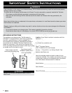
To reduce the risk of tipping of the drawer, the Anti-Tip
block must be properly installed located 14 3/4" above the
floor on which the Microwave In-A-Drawer™ will sit. The
6" Anti-Tip block must be provided by the installer. See
Figures 2, 3 and 4. The Anti-Tip block prevents serious
injury that might result from spilled hot liquids.
If the drawer is ever moved to a different location, the Anti-
Tip block must also be moved and installed. When installed
to the wall, make sure that the screws completely penetrate
the dry wall and are secured in wood or metal so that the
block is totally stable. When fastening, be sure that the
screws do not penetrate electrical wiring or plumbing.
ANTI-TIP BLOCK
Normal Installation Steps
Anti-Tip BLOCK Installation Instructions
DesIgn specIfIcatIons
4"
5"
electrical outletlocation
Anti-Tip
block
(6")
Figure 4