PVS 405D • Connector Wiring 48
RS-232 Connector Wiring
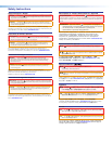
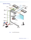
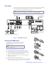
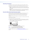
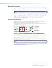
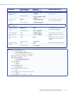
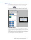
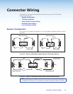
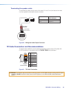
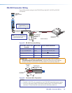
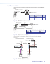
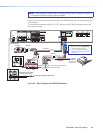
Figure 33 shows the wiring for the PVS 405D and the MLC 104 IP Plus RS‑232
connectors .
MLC 104 IP Plus
right side panel
MLS and
Power
ports
Remote RS-232
Port
RS-232 12V
MLS PWR
AB
Rx
Tx
GROUND
GROUND
+12V IN
G
Ground
+12 VDC input
Ground all devices.
External Power Supply
(12 VDC, 4 A)
NOTE:
If you use cable that has
a drain wire, tie the drain wire
to ground at both ends.
NOTE:
You must connect
a ground wire between
the MLC and PVS 405D.
RS-232
Tx Rx G
Ground (Gnd)
Transmit (Tx)
B
G
Receive (Rx)
A
Transmit (Tx)
Receive (Rx)
B
A
Figure 33. RS-232 Connector Wiring
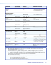
From MLC 104 IP Plus
terminal
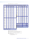
Wire color To PVS 405D terminal
A ‑ (Rx on the MLS port) White A ‑ (Tx on the RS‑232 port)
B ‑ (Tx on the MLS port) Violet B ‑ (Rx on the RS‑232 port)
MLS RS‑232 Ground Drain wire
G ‑ Ground
Power Ground Black To PVS 405D Power Supply
12 V In Red To PVS 405D Power Supply
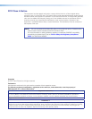
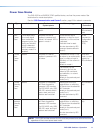
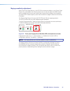
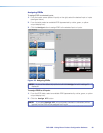
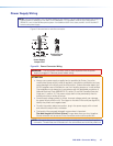
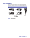
ATTENTION: The length of the exposed (stripped) copper wires is important.
The ideal length is 3/16 inch (5 mm). Longer bare wires can short together.
Shorter wires are not as secure in the connectors and could be pulled out.
3/16"
(5 mm)
Max.
7/8"
Heat Shrink on
Outer Jacket to
Inner Conductor
Transition
ink on
Wire
Figure 34. Connector Wire Preparation
NOTES:
• The MLC 104 IP Plus is powered from the PVS 405D associated power supply.
• Do not tin the power supply wires before installing them in the direct insertion
connector. Tinned wires are not as secure and could be pulled out.