SW2 VGA DA2 A /AF • Installation and Operation
SW2 VGA DA2 A /AF • Installation and Operation
Installation and Operation, cont’d
1
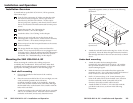
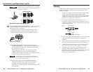
Power supply captive screw connector — Use this 3.5 mm,
2-pole captive screw connector with a 12 VDC, 0.5 to 1 A,
external power supply such as Extron part #70-055-01, which can
be connected to any power outlet from 100 VAC to 240 VAC
operating at 50 Hz or 60 Hz.
Power Connector
0.2” (5 mm) MAX
+
-
SECTION A–A
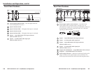
2
Input 1 — 15-pin HD female VGA input connector
3
Input 1 — 3.5 mm female audio input jack
4
Input 2 — 15-pin HD female VGA input connector
(SW2 VGA DA2 A only)
5
Input 2 — 3.5 mm female audio input jack
(SW2 VGA DA2 A only)
6
Output A (Local Monitor) — 15-pin HD female VGA connector
7
Output B — 15-pin HD female VGA connector
8
Audio output connector — Balanced or unbalanced audio can be
output via this 3.5 mm, 5-pole captive screw connector. The
audio output cable should be wired in the following illustration.
Rear Panel Features
SW2 VGA DA2 A
SW2 VGA DA2 AF
POWER
12V
0.2A MAX
12
SW2 VGA DA2 AF
INPUT
1
OUTPUTS
A (LOCAL MONITOR)
B
CONTACT AUTO-SW
POWER
12V
0.2A MAX
12
SW2 VGA DA2 A
INPUT
1
2
OUTPUTS
A (LOCAL MONITOR)
B
CONTACT AUTO-SW
1
22 2
6 7 8 9
4 5
3
2-6
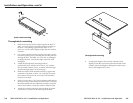
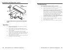
Front Panel Features
AUTO
SWITCH
SW2 VGA DA2 A
1 2
AUTO
SWITCH
SW2 VGA DA2 AF
1 2
2
INPUT
1 2 3 4 5 76
1
Autoswitching indicator LED — This LED lights when the
autoswitching feature is active.
2
Input 1 selection switch
3
Input 1 indicator LED — This lights when input 1 is selected.
4
Input 2 selection switch
5
Input 2 indicator LED — This lights when input 2 is selected.
6
Input 2 — 15-pin HD female VGA input connector
(SW2 VGA DA2 AF only)
7
Input 2 — 3.5 mm female audio input jack
(SW2 VGA DA2 AF only)
2-7