Maintenance
TROUBLESHOOTING
6
6-47
1. Power supplies: +5V dc at U202-1; 0V dc U202-11.
2. µC clock output: 8 MHz at U202-2,-3.
3. Trigger line U202-40 (TP201): Square wave, 50% duty, low 0V, high 3.8V
(nominal). The period of the trigger signal should be 12.500 ms for 60 Hz line.
4. Interrupt from A/D (U202-39): Normally low, duration 48 µs occurs approximately
5450 µs after falling edge of trigger signal on TP201 (U202-40).
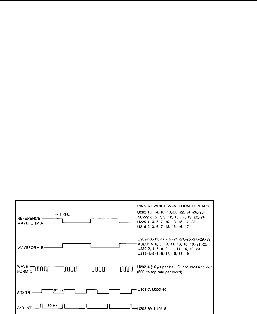
5. Guard-crossing test pattern (U202-4): Waveform C (see Figure 6-10).
6. Interrupts from watchdog timer (U202-6): Pulsed low for 0.2 sec every 1.5 sec,
exponential rise between pulses.
7. Output test patterns (see Waveforms A and B in Figure 6-10): 1 kHz square wave on
indicated pins, 50% duty cycle, low 0V, high 3.8V nominal. (The waveforms are
interrupted every 1.5 sec for 0.2 sec due to interrupts from the watchdog timer.) To
observe these patterns, remove U220, attach a logic clip to address latch U219 and
sync on U219-3 for Reference Waveform A on channel 1 of a dual trace scope.
Compare channel 1 with waveforms at U202-10,-14,-16,-18,-20,-22,-24,-26,-28.
These should all be the same as reference Waveform A (including phase). Then
compare channel 1 with waveforms at U202-13,-15,-17,-19,-21,-23,-25,-27,-29,-
33.These should be the same as Waveform B, which is simply the opposite phase of
Waveform A.
6-43. Address Latch (U219)
Verify that U219-2, -6, -7, -12, -13, -16, -17 are the same as Waveform A (see Figure 6-
10) on U219-3. Verify that U219-4, -5, -8, -9, -14, -15, -18, -19 are the same as
Waveform B. The waveforms should be interrupted every 1.5 sec for 0.2 sec due to
interrupts from the watchdog timer.
f6-10.wmf
Figure 6-10. Waveforms for In-Guard Troubleshooting Mode
6-44. External Program Memory (XU222)
Sync on U219-3. Verify that XU222-3, -5, -9, -12, -15, -17, -19, -23, -24 are the same as
Waveform A (see Figure 6-10) on U219-3. Verify that XU222-4, -6, -8, -10, -11, -13, -
