Maintenance
TROUBLESHOOTING
6
6-59
6-66. A/D Converter Troubleshooting
If there is a failure of the A/D Converter, all power supply levels should be checked at the
op amps (U102 and U103) and the A/D IC (U101). The A/D Converter has a total of
seven supplies: +15V, -15V, +5V, +7.5V, -8.2V, +7.00000V, and -7.00000V. All
supplies should be within 5% of their nominal values except for the +7.00000V and -
7.00000V reference supplies, which should be within +/-1000 ppm and +/-250 ppm
respectively. The bootstrap supplies (lines BS1 and BS2) should be +7V and -7V (+/-
10%) referenced to the + input of the A/D amplifier (U103-3).
Troubleshooting the bootstrap supplies can often be made easier by putting the 8842A in
EX TRIG (to stop the A/D Converter) and connecting the input of the A/D Converter
(TP103) to INPUT LO (Reference Low on the schematic). The bootstrap supplies are
then referenced to instrument common (Reference Low).
NOTE
For the following tests, set the 8842A to the VDC function and the 2V
range, and trigger the oscilloscope from the falling edge of line not-TR
(TP201).
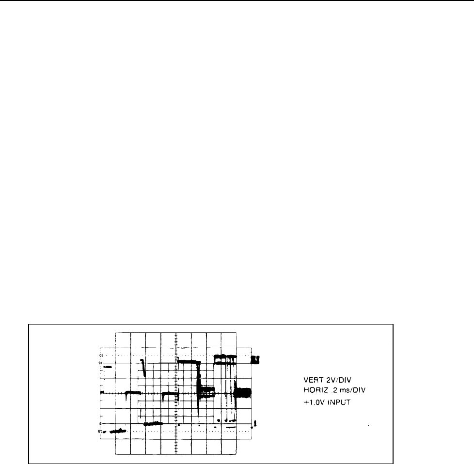
If all supplies are correct, the next most useful troubleshooting tool is the A/D output
waveform at TP101, which can be checked with an oscilloscope. The waveform should
look like the one shown in Figure 6-14 when the input voltage is at 50% of the selected
range. Various portions of the waveform correspond to different parts of the A/D cycle.
By examining the waveform, problems in the A/D Converter can be isolated down to one
or two components.
f6-14.wmf
Figure 6-14. Output of A/D Amplifier (TP101)
