– 8 –
4. Screw the decoring screw (if using the pusher plate feed attachment) (left-hand thread) OR the
agitator device (if using the feed hopper attachment) (left-hand thread) into position in the cutting
tool center.
5. Release the catch, swing the feed cylinder back into position, and raise the locking handle.
If you use the wrong combination of dicing grid and slicing tool (see Cutting Tool Guide), the following
may result:
• The feed cylinder cannot be closed.
• The space between the dicing grid and the slicing tool is too large and leads to poor cutting results.
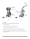
REMOVING THE CUTTING TOOLS
1. Remove the pusher plate feed attachment or the feed hopper attachment (see Installing and
Removing the Feed Attachments in this manual).
2. Pull the locking handle forward and swing the feed cylinder out to the rear.
3.
Using the wrench supplied, loosen the decoring screw OR the agitator device in a clockwise direction.
4. Remove the cutting tool(s) and the ejector plate.
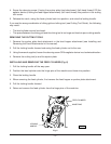
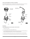
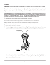
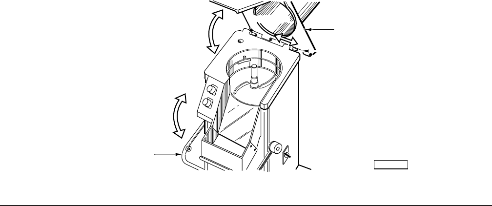
INSTALLING AND REMOVING THE FEED CYLINDER (Fig. 6)
1. Pull the locking handle all the way open.
2. Position the feed cylinder onto the hinge pins of the machine and lower into position.
3. Close the locking handle.
4. When removing the feed cylinder, first remove the feed hopper or pusher plate attachment.
5. Pull the locking handle forward.
6. Raise and remove the feed cylinder from the hinge pins of the machine.
Fig. 6
PL-52968
LOCKING
HANDLE
FEED CYLINDER
HINGE PINS