Return to Section TOC Return to Section TOC Return to Section TOC Return to Section TOC
Return to Master TOC Return to Master TOC Return to Master TOC Return to Master TOC
F-28
TROUBLESHOOTING & REPAIR
F-28
WIRE-MATIC 255
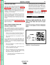
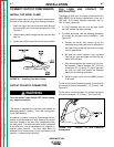
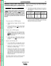
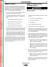
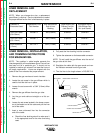
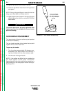
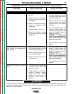
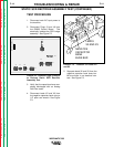
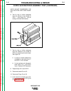
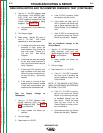
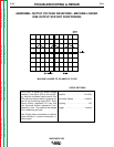
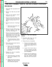
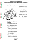
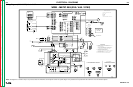
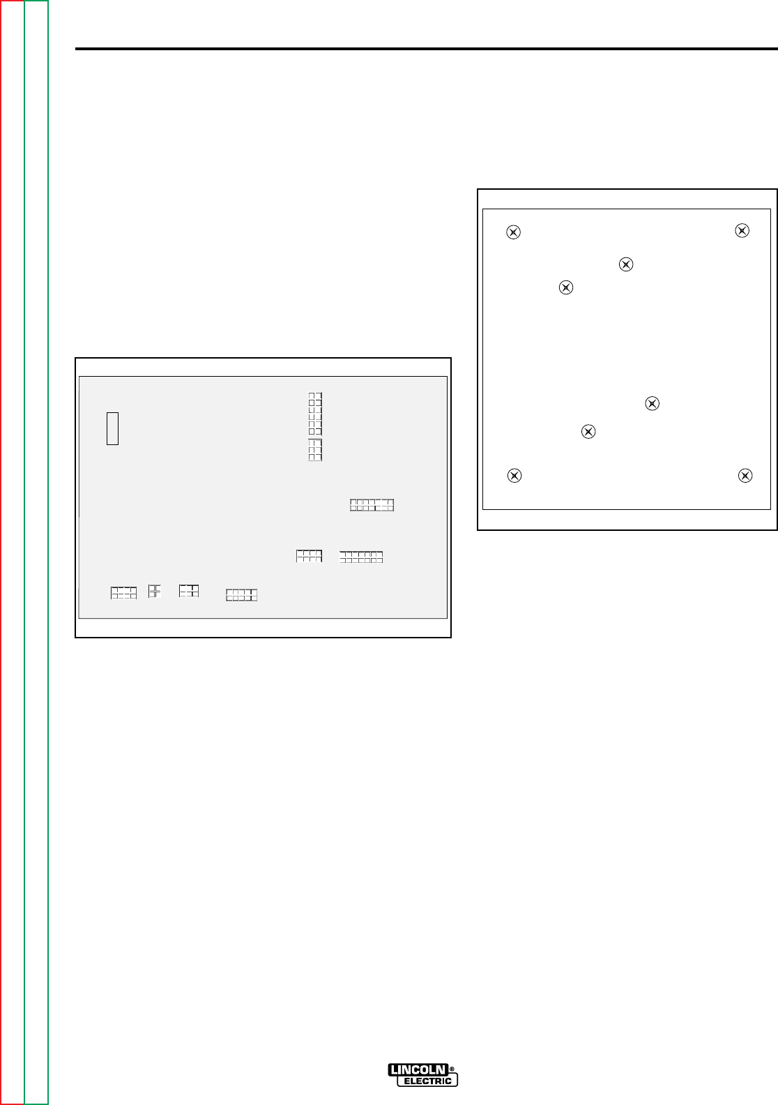
4. Carefully remove the P.C. Board
from the mounting standoffs. See
Figure F.10.
FIGURE F.10 - Control Board
Mounting Locations may vary
with different Code Machines.
5. Lift the Control Board straight up
and out from the machine.
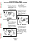
6. When re-installing the Control
Board carefully secure Board to
mounting standoffs.
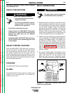
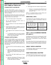
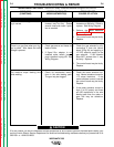
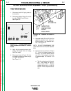
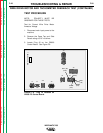
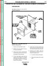
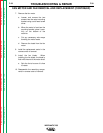
CONTROL PC BOARD REMOVAL AND REPLACEMENT (CONTINUED)
REMOVAL AND REPLACE-
MENT PROCEDURE
1. Disconnect main input power the
machine.
2. Remove the Case Top and Side
Panels using 5/16" nut driver.
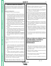
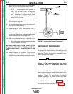
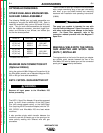
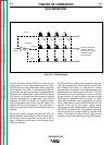
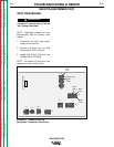
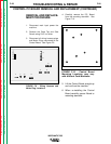
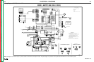
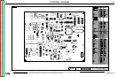
3. Disconnect all wiring harness plugs
and Molex Plugs connected to the
Control Board. See Figure F.9.
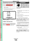
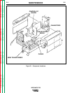
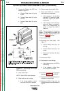
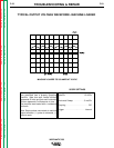
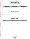
FIGURE F.9 - Wiring Harness and
Molex Plug Locations.
J2
J7
J4
J10
J6
J9
J3
J5
J1
G2803
WM-255 CONTROL