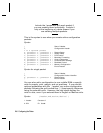
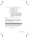
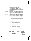
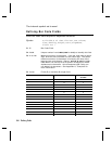
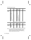
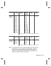
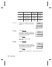
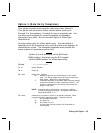
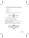
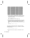
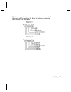
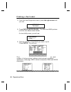
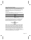
3.
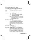
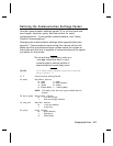
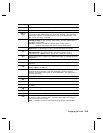
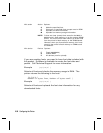
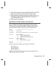
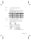
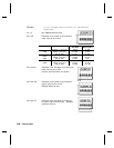
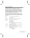
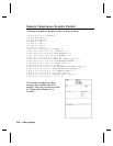
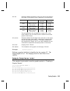
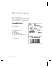
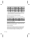
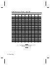
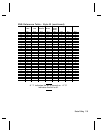
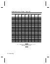
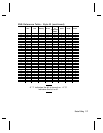
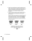
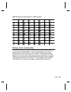
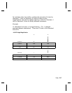
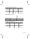
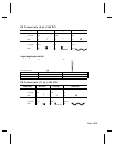
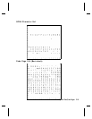
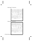
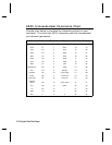
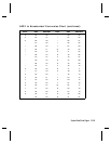
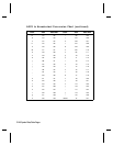
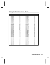
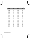
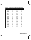
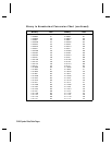
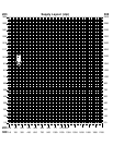
One row at a time, convert each group of eight binary digits to
hex values, using the binary to hex conversion chart found in
Appendix C.
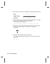
starting at position 49 ...
00111111 = 3F
11111111 = FF
11111111 = FF
11110000 = F0
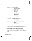
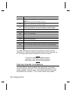
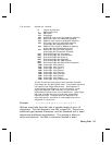
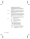
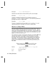
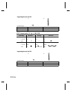
4.
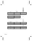
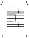
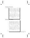
Write the hex values for each row as a continuous string.
row 1, position 49 = 03FFFFFF00000
All hex numbers must be two digits. For
example, write hex 0 as 00, or hex E as 0E.
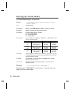
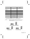
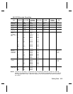
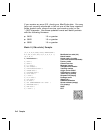
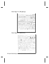
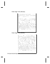
5.
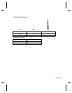
Repeat steps 3 through 4 for each row on the grid.
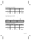
6.
Insert the hex values in syntax format.
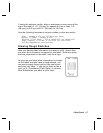
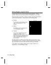
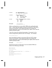
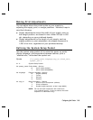
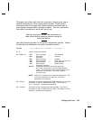
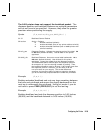
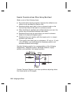
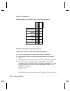
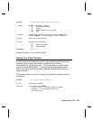
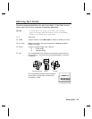
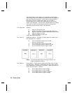
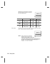
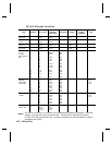
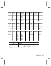
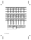
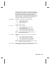
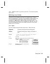
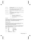
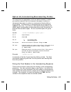
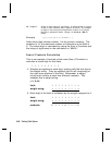
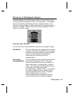
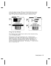
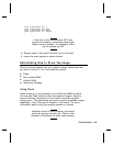
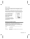
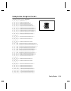
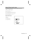
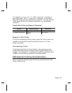
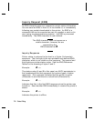
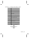
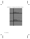
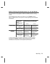
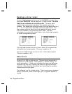
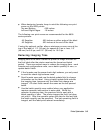
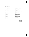
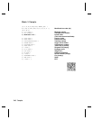
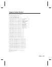
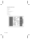
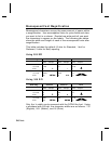
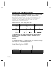
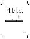
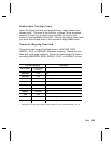
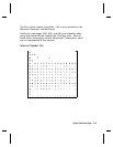
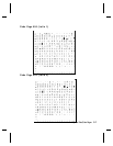
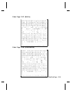
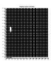
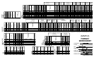
Using the Run Length Encoding Method
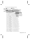
The following steps explain how to derive a run length character
string from a bitmapped graphic.
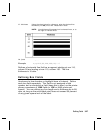
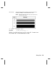
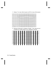
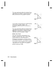
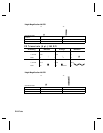
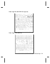
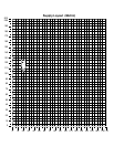
Each square on the grid represents a dot. A black square
indicates the dot is ON, and a white square indicates the dot is
OFF.
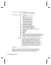
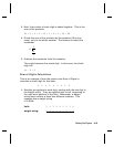
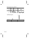
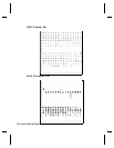
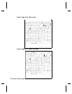
For visual clarity, the following example
shows "1" to indicate when a square is ON,
and "0" to indicate when a square is OFF.
You do not have to convert your dots when
using the run length method.
Creating Graphics
5-7