User’s Manual of WGSW-24040 / WGSW-24040R
SGSW-24040 / SGSW-24040R
23
Lights:
To indicate the link through that port is successfully established with speed
10Mbps or 100Mbps
Blink:
To indicate that the switch is actively sending or receiving data over that port.
10/100
LNK/ACT
Orange
Off:
If 1000 LNK/ACT LED light-> indicate that the port is operating at 1000Mbps
If 1000 LNK/ACT LED Off -> indicate that the port is link down
■ 1000Base-SX/LX SFP interfaces (Shared Port-21~Port-24)
LED Color Function
Lights:
To indicate the link through that SFP port is successfully established with
speed 1000Mbps
1000
LNK
Green
Off:
To indicate that the SFP port is link down
■ 7-Segment LED Display
Stack ID (1~9, A~F, 0): To indicate the Switch ID of each SGSW Managed Switch. Switch IDs are used to uniquely identify
the Managed Switches within a stack. The Switch ID of each Managed Switch is shown on the display on the front of the
Managed Switch and is used widely in the web pages as well as in the CLI commands of the Stack group.
Stack ID 1 2 3 4 5 6 7 8 9 A. B. C. D. E. F. 0
Switch ID 1 2 3 4 5 6 7 8 9 10 11 12 13 14 15 16
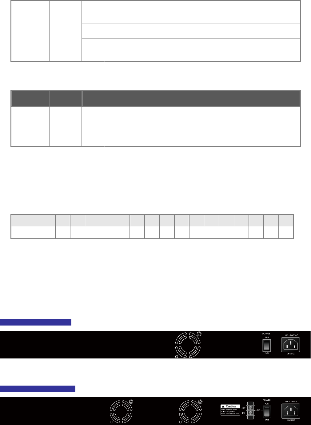
2.1.3 Switch Rear Panel
The rear panel of the Managed Switch indicates an AC inlet power socket, which accept input power from 100 to 240V AC,
50-60Hz. Figure 2-5 to Figure 2-8 shows the rear panel of these Managed Switches
WGSW-24040 Rear Panel
Figure 2-5 Rear panel of WGSW-24040
WGSW-24040R Rear Panel
Figure 2-6 Rear panel of WGSW-24040R


