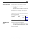
Rockwell Automation Publication 1734-UM001E-EN-P - July 2013
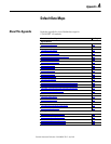
Default Data Maps 175
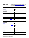
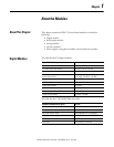
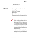
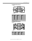
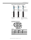
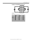
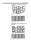
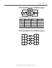
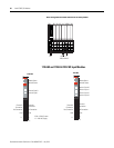
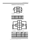
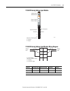
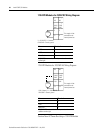
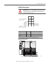
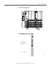
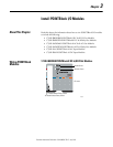
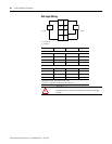
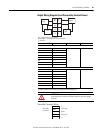
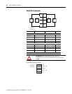
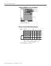
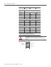
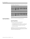
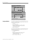
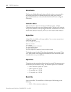
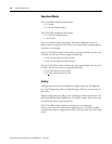
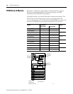
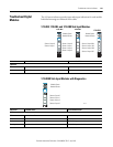
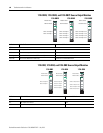
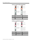
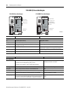
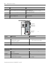
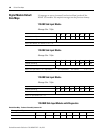
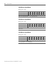
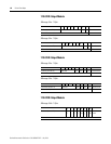
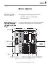
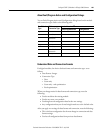
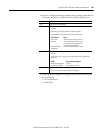
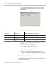
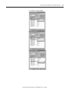
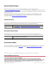
1734-OE2C Analog Current Output Module
Message Size: 4 bytes
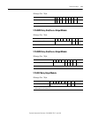
Message Size: 2 Bytes
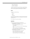
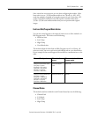
Channel Status
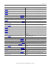
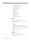
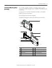
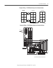
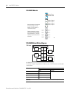
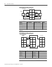
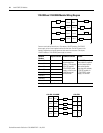
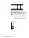
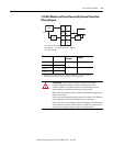
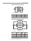
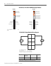
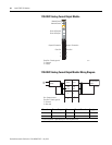
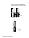
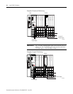
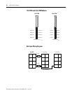
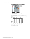
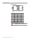
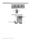
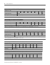
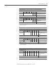
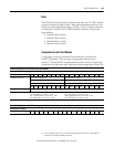
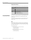
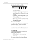
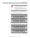
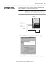
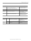
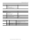
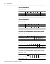
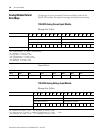
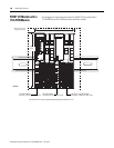
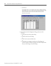
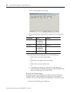
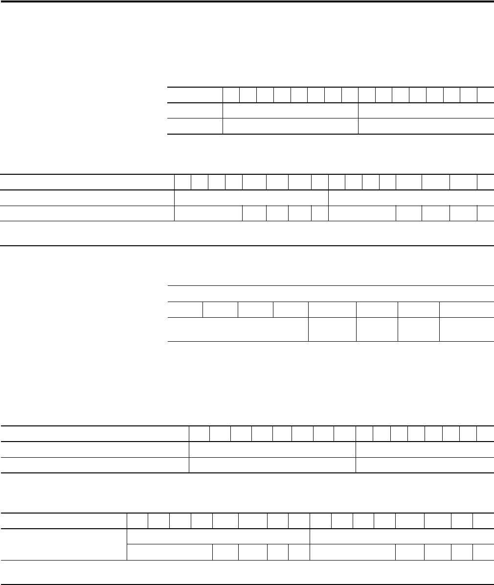
1734-OE2V Analog Voltage Output Module
Message Size: 4 bytes
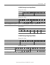
Message Size: 2 Bytes
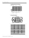
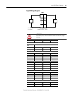
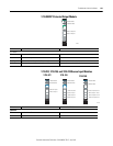
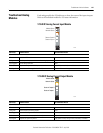
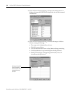
15 14 13 12 11 10 09 08 07 06 05 04 03 02 01 00
Consumes (Tx) Output Channel 0 High Byte Output Channel 0 Low Byte
Output Channel 1 High Byte Output Channel 1 Low Byte
15 14 13 12 11 10 09 08 07 06 05 04 03 02 01 00
Produces (Rx) High Byte - Channel 1 Status Low Byte - Channel 0 Status
Not used HCA LCA CM CF Not used HCA LCA CM CF
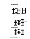
Where: CF = Channel Fault status 0 = no error 1 = fault CM = Calibration Mode 0 = normal 1 = calibration mode
LCA = Low Clamp Alarm 0 = no error 1 = fault HCA = High Clamp Alarm 0 = no error 1 = fault
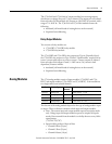
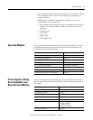
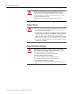
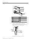
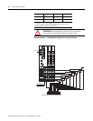
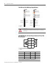
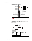
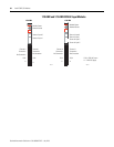
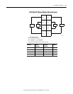
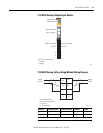
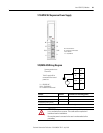
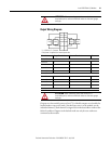
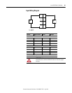
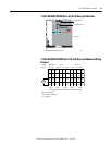
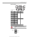
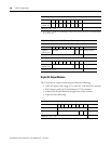
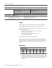
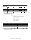
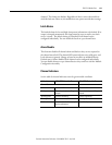
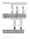
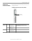
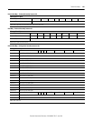
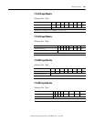
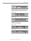
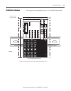
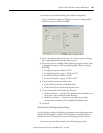
Channel Status Bytes
Bit 7 Bit 6 Bit 5 Bit 4 Bit 3 Bit 2 Bit 1 Bit 0
Not used High Clamp Low
Clamp
CAL Mode Channel Fault
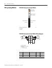
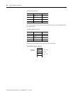
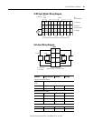
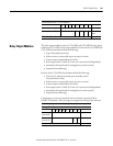
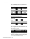
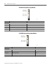
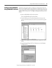
15 14 13 12 11 10 09 08 07 06 05 04 03 02 01 00
Consumes (scanner Tx) Output Channel 0 High Byte Output Channel 0 Low Byte
Output Channel 1 High Byte Output Channel 1 Low Byte
15 14 13 12 11 10 09 08 07 06 05 04 03 02 01 00
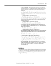
Produces (scanner Rx) Channel 1 Status - High Byte Channel 0 Status - Low Byte
Not used HCA LCA CM ST Not used HCA LCA CM ST
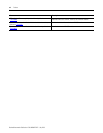
Where: ST = Channel Fault Status; 0 = no error, 1 = fault CM = Calibration Mode; 0 = normal, 1 = calibration mode
LCA = Low Clamp Alarm; 0 = no error, 1 = fault HCA = High Clamp Alarm; 0 = no error, 1 = fault