© Titan Tool Inc. All rights reserved. 27
4. Remove the motor/pump block, 37)( o-ring (3), upper
packing spring (5), and upper packing set (4).
5. Hold the displacement rod (6) in a vise by the flats at the
top of the displacement rod and remove the piston seat
(11) with a wrench while holding the displacement rod
horizontal with wooden support, if necessary. Remove the
ball (10), lower packing set (4), lower packing spring (9),
sleeve (8), and spring retainer (7).
6. Remove the ball cage (14), 37)( o-ring (3), and ball (15).
7. Replace the connecting pin (2) and retainer ring (1) .
8. Remove the o-ring (13) from the pump cylinder (12)
Reassembly
1. Place the ball (15) into the foot valve (16), followed by the
ball cage (14).
2. Insert the 37)( o-ring (3) into the lower groove of foot
valve (16).
3. Place the lower packing set (4) onto the piston seat (11)
with the peak of the “V” packings pointing down toward
the foot valve.
4. Clean the threads on the piston seat (11) and coat the
threads with blue Loctite. Make sure no Loctite is on the
seat.
5. Place the ball (10) onto the piston seat (11).
6. Place the lower packing spring (9) onto the piston seat
(11), followed by the sleeve (8) and the spring retainer (7).
7. Screw the displacement rod (6) and the piston seat (11)
together. Tighten in a vise to 75 ft./lbs.
8. Insert the 37)( o-ring (3) into the upper grove of the
motor/pump block.
9. Insert the upper packing set (4) into the motor/pump block
with the peak of the “V” packings pointing up toward the
motor.
10. Place the upper packing spring (5) into the motor/pump
block with the small tapered end facing up toward the
motor/pump block.
11. Insert the displacement rod (6) up through the upper
packings in the motor/pump block.
12. Align the holes in the displacement rod (6) and the
hydraulic piston rod and insert the connecting pin (2).
13. Thread the short threads of the pump cylinder (12) into
the motor/pump block and tighten with a strap wrench.
14. Place the o-ring (13) onto the top grove of the pump
cylinder (12).
15. Thread the foot valve (16) onto the pump cylinder (12),
tighten with a strap wrench, then back off to align the
siphon hose.
NOTE: It is not necessary to over-tighten the foot
valve. O-ring seals perform sealing function
without excessive tightening. Full thread
engagement is sufficient. The foot valve may
be rotated backward up to 1/2 turn from full
engagement for convenient hose position.
For siphon hose attachment, it is critically
important that the threads of the siphon hose
fit snugly into the foot valve with the hose
assembly couplings 37)( taped and sealed to
prevent air leakage.
NOTE: The packings must be soaked in oil before
installation.
NOTE: The packings must be soaked in oil before
installation.
NOTE: Use 37)( tape on all threaded pipe
connections.
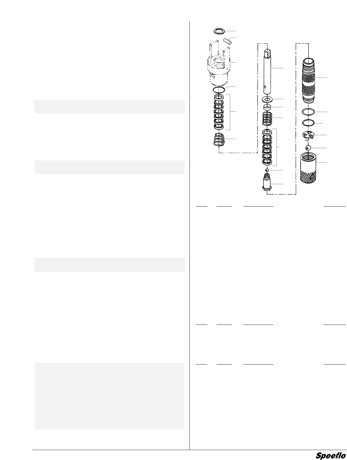
Item
Part # Description Quantity
1 143-019 Retainer ring.............................................1
2 107-003 Connecting pin .........................................1
3 106-015 O-ring, 37)(............................................2
4 106-002 Packing set, leather/UHMPWPE/steel .....2
5 106-005 Upper packing spring, SS ........................1
6 108-021 Displacement rod, Severe Service 500.......1
7 106-001 Spring retainer..........................................1
8 106-116 Sleeve ......................................................1
9 106-016 Lower packing spring, SS ........................1
10 569-021 Ball, SS.....................................................1
11 106-011 Piston seat................................................1
12 108-940 Pump cylinder, Severe Service 500 .........1
13 106-014 O-ring .......................................................1
14 106-012 Ball cage, SS............................................1
15 138-340 Ball, SS.....................................................1
16 107-013 Foot valve assembly ................................1
Pump Service Kit, Major (P/N 107-501)
Item Part # Description Quantity
6 108-021 Displacement rod .....................................1
12 108-940 Pump cylinder...........................................1
107-051 Pump Service Kit, Minor...........................1
Pump Service Kit, Minor (P/N 107-051)
Item Part # Description Quantity
1 143-019 Retainer ring.............................................1
3 106-015 O-ring, 37)(............................................2
4 106-002 Packing set, leather/UHMWPE/steel........2
10 569-021 Ball, SS.....................................................1
13 106-014 O-ring .......................................................1
15 138-340 Ball, SS.....................................................1
426-051 Loctite sealant ..........................................1
1
Motor/
Pump
Block
5
6
7
8
9
10
11
12
13
3
14
15
16
4
4
2
3


