www.desatech.com
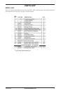
105116-01D12
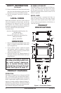
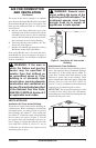
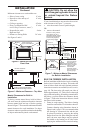
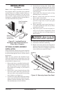
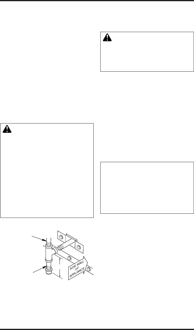
If a sediment trap is not incorporated as a part of
the gas utilization equipment, one shall be installed
as close to the inlet of the equipment as practical at
the time of installation, as per ANS Z223.1/NFPA
54. See Figure 14.
Prepare incoming black iron gas line with Teon
tape or pipe joint compound (check with local
codes as to the use of Teon tape). Compounds
used on threaded joints of gas piping shall be
resistant to the action of propane/LP and should
be applied lightly to ensure excess sealant does
not enter the gas line.
Complete your gas installation by connecting
the incoming gas line to the appliance regulator.
Secure all joints tightly with wrench but do not
overtighten. If a exible gas line is used, take care
not to kink the connector.
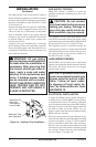
WARNING: All gas piping
andconnectionsmustbetested
forleaksaftertheinstallationis
completed.Afterensuringthat
themanualshutoffgasvalveis
open, apply a soap and water
solution to all connections and
joints.Ifbubblesappear,leaks
can be detected and corrected.
DO NOT USE OPEN FLAME FOR
LEAK TESTING AND DONOT
OPERATE ANY APPLIANCE IF
ALEAKISDETECTED.
INSTALLATION
Continued
Figure 14 - Sediment Trap Installation
Incoming 1/2"
Gas Line
Permitted by
Local Codes
Sediment Trap
(Not Supplied)
GAS SUPPLY TESTING
Note: This section is intended as a guide for
qualied technicians installing gas to this vent-
free rebox.
CAUTION: Do not connect
vent-free heater before pressure
testinggaspiping.Damageto
gasvalvemayresultandanun-
safeconditionmaybecaused.
The appliance and its’ individual shutoff valve
must be disconnected from the gas supply piping
system during any pressure testing of that system at
test pressures in excess of 1/2 psig (3.5 kPa).
The appliance must be isolated from the gas
supply piping system by closing manual shutoff
valve during any pressure testing of the gas sup-
ply piping system at test pressures equal to or
less than 1/2 psig (3.5 kPa).
HARD-WIRING FIREBOX
Model FBST can be hard-wired to the duplex
outlet located inside the rebox bottom if desired.
This allows the blower accessory to be plugged
into the duplex outlet.
NOTICE:Aqualiedelectrician
mustconnectelectricalwiringto
duplex outlet for built-in instal-
lation. Follow all local codes.
In absence of local codes fol-
low The National Electric Code
ANS/NFPA 70.
ELECTRICAL INSTALLATION
A model GA3500A blower system assembly is
available for use with the FBST vent-free rebox
as an optional accessory. This blower is designed
to be installed on either side of the FBST rebox,
when provisions for a 120 VAC supply connection
are made at either end of the cabinet. Use of a
blower system other than those manufactured by
DESA voids the warranty.
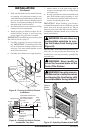
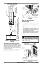
Electrical connections are made within the recep-
tacle with wires that are routed through the bushing
provided (see Figure 15, page 13). The receptacle
may be relocated to either side, when necessary.
However, the cover plate must be replaced over the
unused access point. Be certain to properly ground
the vent-free rebox using the green grounding
wire (see Figure 17 on page 14).