


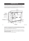
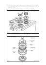

Fig. 7A DESN 512920
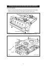
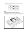
4. Position burner caps onto burner bodies. (See Figs. 7A, 7B & 7C)
15
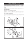
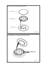
ULTRA RAPID BURNER
Fig. 6C DESN 512419
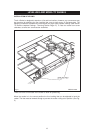
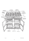
3. Fit and secure six burner rings using M4 screws on rear left hand, front centre, front right
hand and rear right hand burners. Use No.6 3/8 screw on front left hand and centre rear
burners. (See Fig. 6C).
NOTE: The fitting of LH and centre burners are the same as shown in Fig. 6B.