


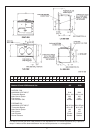
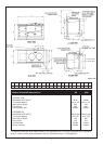
The terminal is suitable for wall thicknesses from 228mm
to 600mm cut size
Should the installation of the appliance be in an unusual
location or restricted space, special procedures may be
necessary.
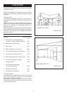
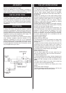
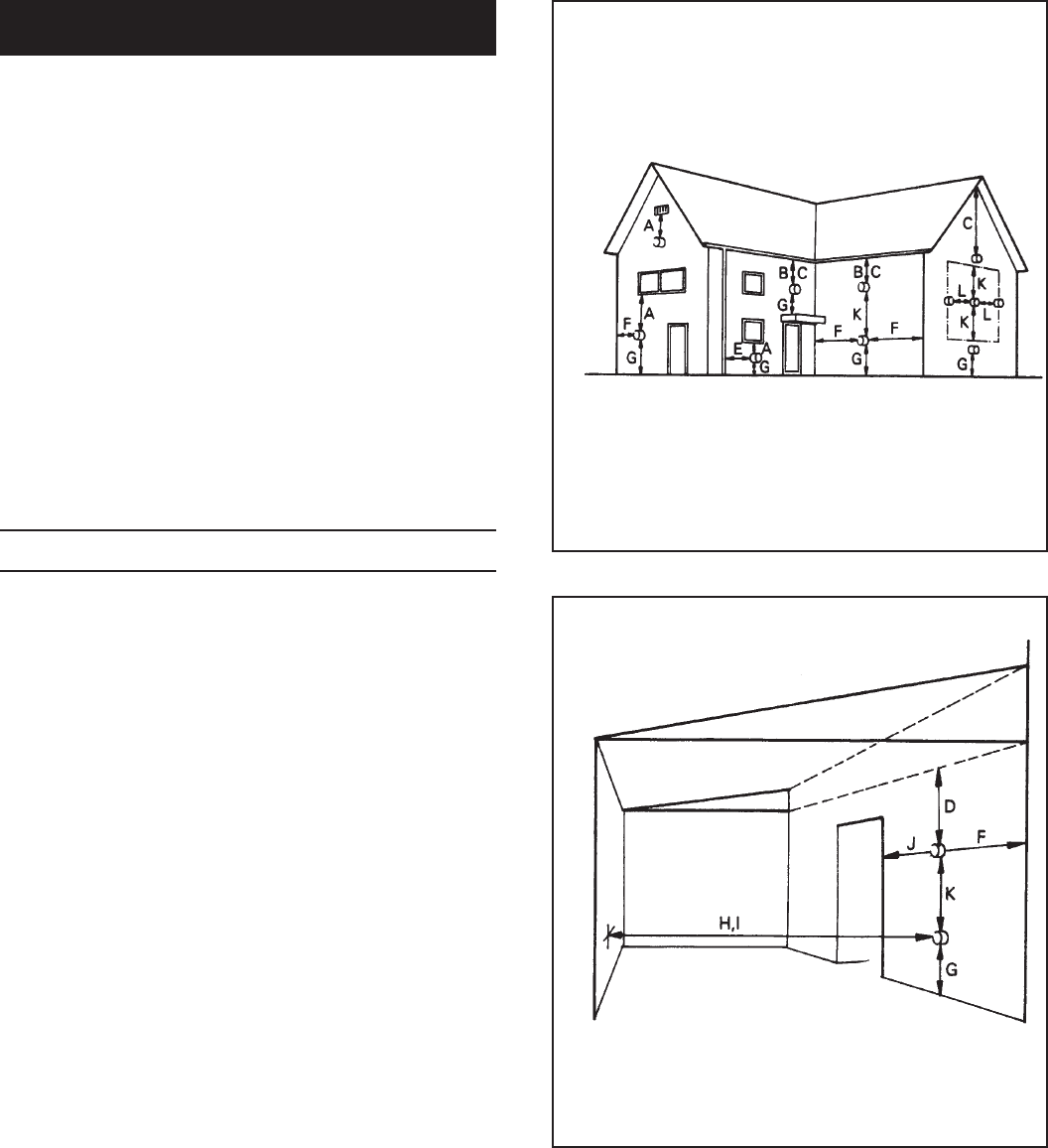
Terminal Position
The minimum acceptable spacings from the terminal to
obstructions and ventilation openings are as shown in the
diagram.
Where the terminal is fitted within 600mm below plastic
guttering an aluminium shield 1500mm long should be
fitted to the underside and immediately beneath the
guttering or eaves.
Where the terminal is fitted within 450mm below eaves or
painted guttering an aluminium shield 750mm long should
be fitted to the underside and immediately beneath the
guttering or eaves.
Minimum siting dimensions for Balanced Flue terminals
Position Minimum Spacing
mm
A Directly below an openable window,
air vent, or an other ventilation opening 300
B Below gutter, drain/soil pipe 300
C Below eaves 300
D Below a balcony or car port roof 600
E From vertical drain pipes and soil pipes 300
F From internal or external corners 600
G Above adjacent ground or balcony level 300
H From surface facing the terminal 600
I Facing terminals 600
J From opening (door/window)
in car port into dwelling 1200
K Vertical from a terminal 1500
L Horizontally from a terminal 300
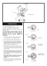
Terminal Protection
A terminal guard is supplied with the cooker and must be
fitted if flue termination is less than 2 metres above
ground level, or subject to damage.
When fitted, it must be positioned to provide a minimum
of 50mm clearance from any part of the terminal and be
central over the terminal.
4
FLUE SYSTEM
AROUND THE HOUSE
DESN 511052
UNDER CAR PORT, ETC.
DESN 511053