


Page 10 of 13 506252-01Issue 0902
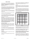
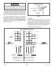
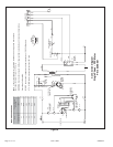
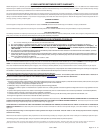
Figure 8
Connection Diagram
Single Phase – PSC Motor
P/N 48396-001
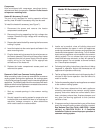
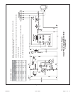
Unit
FactoryShipped
Settings
Cooling Input (BLK)
24 LOW
30 MED
36 HIGH
42 LOW
48 MED
60 HIGH
BLOWER SPEED CHART
208/230V-1-60
G
W1
C
R
BLK
RED
YEL
RED
CONTACTOR
THERMOSTAT
L1
T1
T2
L2
C
H
F
CONDENSER
FAN MOTOR
COMPRESSOR
CONTACTOR
COMPRESSOR
CONTACTOR
DUAL
CAPACITOR
COMPRESSOR
TRANSFORMER
C
S
R
WHT
L2
L1
BLK
BRN
PUR
RED
RED
BLK
208V
240V
24V
INDOOR
BLOWER
MOTOR
S1
K1
T1
B3
B4
K1-2
C12
B1
K1-1
BLU
YEL
C4
CAPACITOR
H
M
L
C
SEE CHART
FOR WIRING
NO
NC
C
BLOWER
CONTROL
A15
BLK
C
G
XFMR-R
R
XFMR-C
FUSE
Y
A15
BLOWER
GRN
RED
BLU
BLU
YEL
BLU
BLK
BLK
WHT
P-1
P-2
P-4
P-6
P-5
BLU
YEL
YEL
HIGH PRESSURE
SWITCH
(IF USED)
S4
GRN
RED
YEL
P-3
BLU
L
MOTOR
SPEED TAPS
CHM
CONTROL
NOTE - If any of the original wire is replaced, the same size and type wire must be used.
Use copper conductor only, min. 75°C wire.
WARNING - Electric shock hazard. Unit must be grounded in accordance with national and local codes.
Line voltage field installed.
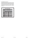
W1 & W2 can be used to stage electric heat accessory on 15 & 20kW models.
5, 7.5, & 10kW heater accessories function off W1 only.