


506252-01 Page 5 of 13Issue 0902
Power supply to the unit must comply with all applicable codes
and the National Electical Code (NEC) or Canadian Electrical
Code (CEC). A fused disconnect switch should be field provided
for the unit. The switch must be separate from all other circuits.
If any of the wire supplied with the unit must be replaced,
replacement wire must be of the type shown on the wiring
diagram. Electrical wiring must be sized to carry minimum
circuit ampacity marked on the unit. Use copper conductors
only. Each unit must be wired with a separate branch circuit
and be properly fused.
Thermostat
The room thermostat should be located on an inside wall
where it will not be subject to drafts, sun exposure, or heat
from electrical fixtures or appliances. Follow the
manufacturer’s instructions enclosed with thermostat for
general installation procedure. Color-coded insulated wires
(#18 AWG) should be used to connect thermostat to unit.
Four wires are required for cooling.
Unit must be grounded in accordance with
national and local codes. Failure to ground unit
properly can result in personal injury or death.
WARNING
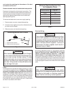
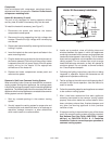
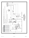
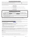
Figure 6
Typical Wiring Connections
RR
CC
CC
RR
L2 L1
YY Y1
Y
L1L2L3
POWERWIRING
208/230-1-60
(75°C MIN.WIRE)
POWERWIRING
24V CONTROLWIRING
(NEC CLASS 2)
TYPICAL WIRING CONNECTION
1 PHASE
GROUND
SCREW
THERMOSTAT
OUTDOOR UNIT
THERMOSTAT
OUTDOOR UNIT
GROUND
SCREW
POWERWIRING
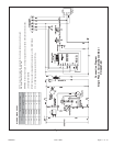
200/230-3-60, 460/575-3-60
(75°C MIN.WIRE)
24V CONTROLWIRING
(NEC CLASS 2)
POWERWIRING
TYPICAL WIRING CONNECTION
3 PHASE
* W1,W2 CAN BE USEDTO STAGE ELECTRIC
HEAT ACCESSORY ON MODELS.15 & 20 KW
* 5 & 10 KW HEATER ACCESSORY FUNCTION
W1 ONLY.OFF
* W1,W2 CAN BE USEDTO STAGE ELECTRIC
HEAT ACCESSORY ON 15 & 20 KW MODELS.
* 10 KW HEATER ACCESSORY FUNCTION OFF
W1 ONLY.
ECONOMIZER
NOT
INSTALLED
ECONOMIZER
W1
W
W
W1
G G
GG
W2
Y2
W2
BLUE
YELLOW
YELLOW
GREEN
BLACK
Do not connect connections except when
required by the indoor thermostat. Refer to the
thermostat installation instructions.
C
CAUTION
Do not connect connections except when
required by the indoor thermostat. Refer to the
thermostat installation instructions.
C
CAUTION
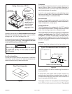
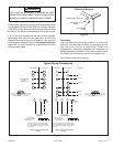
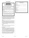
Figure 5
Electrical Access
Heater Power Entry
Thermostat
Entry
Line Voltage
Entry