


13
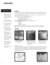
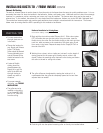
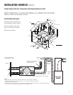
3 Push the hood into
the opening. Attach
the hood to the
outside wall with
mounting screws.
Repeat the
installation procedure
for both the Supply
and Exhaust hood.
2 Pull the insulated
flexible duct through
the opening until it is
well extended and
straight. Slide the
duct’s inner vinyl
sleeve over the hood
collar and secure, pull
the insulation over
the duct and then the
vapor barrier over the
sleeve and secure
with duct tape.
4 Using a caulking
gun, seal around
both hoods to
prevent any
leaks.
1 Using the collar of
the outside hood,
outline the intake &
exhaust holes to be
cut. The holes should
be slightly larger
than the collar to
allow for the
thickness of the
insulated flexible
duct. Cut a hole
for both the intake
and exhaust hoods.
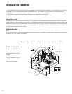
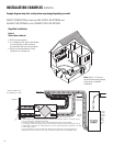
•Decide where your intake and
exhaust hoods will be located.
PRACTICAL
TIPS
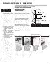
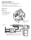
INSTALLING DUCTS GOING TO / FROM OUTSIDE
A well designed and installed ducting system will allow the HRV to operate at its maximum efficiency.
Always try to keep duct runs as short and straight as possible.
See Installation Diagrams for installation examples.
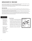
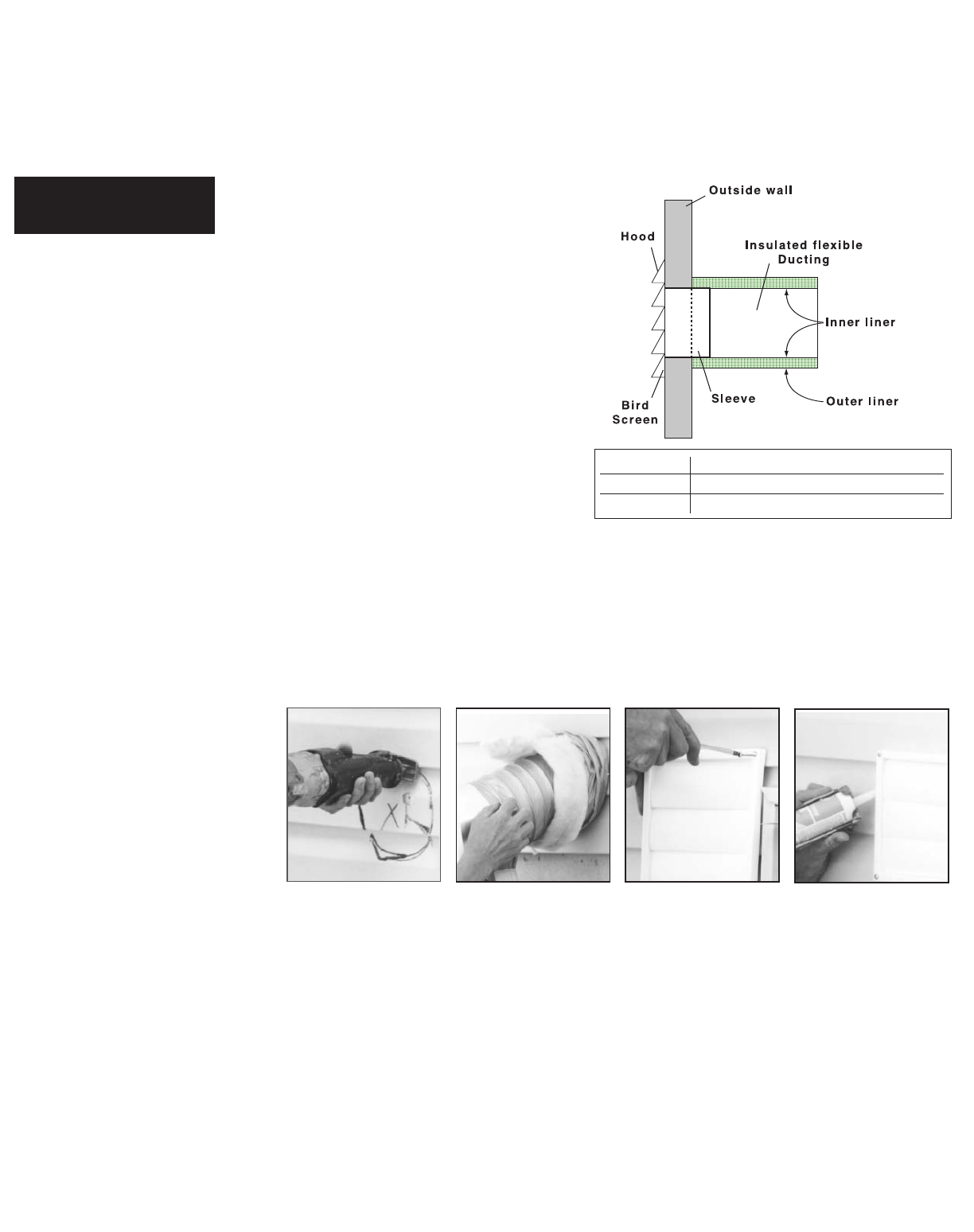
INSTALLING THE DUCTING
TO THE WEATHERHOODS
The inner liner of the flexible insulated duct
must be clamped to the sleeve of the weath-
erhoods (as close to the outside as possible)
and to the appropriate port on the HRV. The
insulation should remain full and not be
squished. The outer liner, which acts as a
vapor barrier must be completely sealed to
outer wall and the HRV using tape and or
caulking. A good bead of high quality caulk-
ing (preferably acoustical sealant) will seal
the inner flexible duct to both the HRV port
and the weatherhood prior to clamping.
To minimize air flow restriction, the flexible
insulated duct that connects the two outside
weatherhoods to the HRV should be
stretched tightly and be as short as possible.
Twisting of folding the duct will severely
restrict air flow.
Locating the Intake
Weatherhood
• Should be located upstream
(if there are pr
evailing winds)
from the exhaust outlet
• At least 4' - 6’ (2m) from the
exhaust weatherhood
• At least 6’ (2m) away from
dryer vents and furnace
exhaust ( medium or high effi-
ciency furnaces)
• A minimum of at least 6’ (2m)
from driveways, oil fill pipes,
gas meters, or garbage con-
tainers
• At least 18” (457mm) above
the ground, or above the
depth of expected snow accu-
mulation
• At least 3’ (1m) from the cor-
ner of the building
• Do not locate in a garage,
attic or crawl space
Locating the Exhaust
Weatherhood
• At least 4' - 6’ (1m - 2m)
from the ventilation air intake
• At least 18” (457mm) above
ground or above the depth of
expected snow accumulation
• At least 3’ (1m) away from
the corner of the building
•
Not near a gas meter, electric
meter or a walkway where fog
or ice could create a hazard
• Not into a garage, workshop
or other unheated space
When installing the weather-
hood, it’s outside perimeter
must be sealed with exterior
caulking.
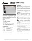
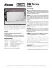
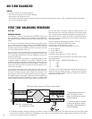
Model Description
SEH-6P Supply & Exhaust Plastic Hood Kit
SEH-6M Supply & Exhaust Metal Hood Kit
* Application for Supply or Exhaust