


3
3. Power Switch (labeled POWER SW) connects to the PWR connector on the
motherboard.
4. Power LED (labeled POWER LED) connector is located behind the Reset
connector on all LED’s, the colored wire is positive (+).
5. Hard Drive LED I, LED II (labeled HDD I, HDD II) connectors: This case comes
with two HDD LEDs. You may use these LEDs for two hard drives.
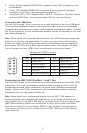
Connecting the USB Ports
You will find a single 10-pin connector on a cable attached to the front USB ports.
This is an Intel standard connector that is keyed so that it can’t be accidentally
reversed when connected to a proper Intel® standard motherboard header. Connect
the 10-pin connector to your motherboard headers so that the blocked pin fits over
the missing header pin.
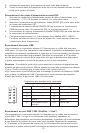
Note: Please check your motherboard manual for your USB header pin layout and
make sure it matches the table below. If it does not match this Intel® standard,
please visit Antec store at http://www.antec.com/StoreFront.bok and search for
part number 30095 to buy a USB internal adapter cable. This adapter will allow
you to connect the front USB to your motherboard on a pin-by-pin basis.
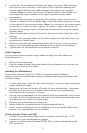
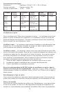
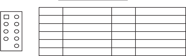
Motherboard USB Pin Layout
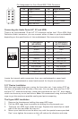
Connecting the IEEE 1394 (FireWire®, i.Link®) Port
You will find a single 10-pin connector on a cable attached to the front IEEE 1394
connection. This is an Intel standard connector that is keyed so that it can’t be
accidentally reversed when connected to a proper Intel® standard motherboard
header. Connect the 10-pin connector to your motherboard header so that the
blocked pin fits over the missing header pin.
Note: Please check your motherboard manual for your IEEE 1394 header pin
layout and make sure it matches the table below. If you intend to connect the
front FireWire port to an IEEE 1394 add-on card that comes with an external-type
IEEE1394 connector, please visit Antec store at http://www.antec.com/Store-
Front.bok and search for part number 30031 to buy FireWire® internal adapter.
This adapter will allow you to connect the front IEEE 1394 port to the external-
type connector.
Pin Signal Names Pin Signal Names
1
USB Power 1
2
USB Power 2
3
Negative Signal 1
4
Negative Signal 2
5
Positive Signal 1
6
Positive Signal 2
7
Ground 1
8
Ground 2
9
Key (No Connection)
10
Empty Pin
12
109