


4
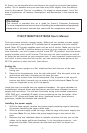
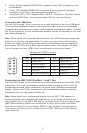
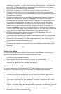
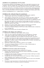
Pin Assignment for Front Panel IEEE 1394 Connector
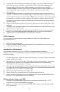
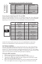
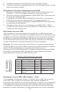
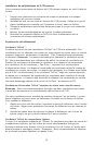
Connecting the Audio Ports (AC’ 97 and HDA)
There is an Intel standard 10-pin AC’ 97 connector and an Intel 10-pin HDA (High
Definition Audio) connector, you can connect either of them to your motherboard
depending on the specification of the motherboard. See instruction below:
Locate the internal audio connectors from your motherboard or sound card.
Consult your motherboard or sound card manual for the pin-out positions.
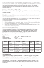
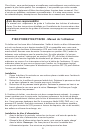
3.5” Device Installation
With the front bezel facing you, swing the front door out. It can swing 270º so
the door will parallel with the side of the case. You can see there are four 5.25”
and one 3.5” external drive bays. Inside the case there are two 3.5” drive cages,
which can house up to six hard drives. Note: We recommend using the lower HDD
cage to get the maximum possible cooling and quiet computing.
The Upper HDD Installation
1. Remove the thumbscrew holding the upper HDD cage.
2. Pull the HDD cage from its position by pulling the ring towards you.
3. There are two HDD trays inside the cage. Squeeze the metal clips on each
side of the tray and slide the tray out.
4. Mount your hard drive into the drive tray with the special screws provided.
Don’t over-tighten the screws as this will reduce the vibration and noise
Pin Signal Names Pin Signal Names
1 TPA+ 2 TPA–
3 Ground 4 Ground
5 TPB+ 6 TPB–
7 +12V (Fused) 8 +12V (Fused)
9 Key (No Pin) 10 Ground
12
10
9
Pin Pin Assignment
(HD AUDIO)
Pin Pin Assignment
(AC’97 AUDIO)
1 MIC2 L 1 MIC In
2 AGND 2 GND
3 MIC2 R 3 MIC Power
4 AVCC 4 NC
5 FRO-R 5 Line Out (R)
6 MIC2_JD 6 Line Out (R)
7 F_IO_SEN 7 NC
8 Key (no pin) 8 Key (no pin)
9 FRO-L 9 Line Out (L)
10 LINE2_JD 10 Line Out (L)
1
2
3579
46
10