


ASUS P2L97 User’s Manual 11
III. INSTALLATION
Jumpers
1) CLRTC p. 13 Real Time Clock (RTC) RAM (Short/Clear CMOS)
2) KB_UP p. 13 Keyboard Power Up
3) FS0, FS1, FS2 p. 14 CPU External Clock (BUS) Frequency Selection
4) BF0, BF1, BF2, BF3 p. 14 CPU”BUS Frequency Ratio
Expansion Slots/Sockets
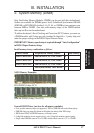
1) System Memory p. 15 System Memory Support
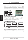
2) DIMM Sockets p. 16 DIMM Memory Module Support
3) SEC CPU Slot p. 19 Single Edge Contact CPU Support
4) SLOT1, SLOT2 p. 24 16-bit ISA Bus Expansion Slots
*
5) PCI1, 2, 3, 4, 5 p. 24 32-bit PCI Bus Expansion Slots
6) AGP p. 25 Accelerated Graphics Port
Hardware Monitor
1) JP1 p. 22 Pentium II Processor Thermal Sensor Connector
Connectors
1) PS2KEYBOARD p. 26 PS/2 Keyboard Connector (6-pin female)
2) PS2MOUSE p. 26 PS/2 Mouse Connector (6-pin female)
3) PRINTER p. 27 Parallel (Printer) Port Connector (25-pin female)
4) COM1, COM2 p. 27 Serial Port COM1 & COM2 (two 9-pin male)
5) FLOPPY p. 27 Floppy Drive Connector (34-pin block)
6) USB p. 28 Universal Serial BUS Ports 1 & 2 (two 4-pin female)
7) Primary / Second IDE p. 28 Primary / Secondary IDE Connector (40-pin blocks)
8) IDELED p. 29 IDE LED Activity Light (2 pins)
9) CHA_, PWR_, CPU_FAN p. 29 Chassis, Power Supply, CPU Fan Power Lead (3-pin block)
10) IR p. 30 Infrared Port Module Connector (5 pins)
11) ATXPWR p. 30 ATX Motherboard Power Connector (20-pin block)
12) WOL p. 31 Wake on LAN Connector (3 pins) (Reserved)
13) MSG LED (PANEL) p. 32 System Message LED (2 pins)
14) SMI (PANEL) p. 32 SMI Switch Lead (2 pins)
15) PWR SW (PANEL) p. 32 ATX Power & Soft-Off Switch Lead (2 pins)
16) RESET (PANEL) p. 32 Reset Switch Lead (2 pins)
17)
PWR LED (
PANEL
)
p. 32 System Power LED Lead (3 pins)
18)
KEYLOCK (
PANEL
)
p. 32 Keyboard Lock Switch Lead (2 pins)
19) SPEAKER (PANEL) p. 32 Speaker Output Connector (4 pins)
*
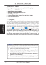
The onboard hardware monitor uses the address 290H-297H so legacy ISA cards must not
use this address otherwise conflicts will occur.
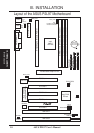
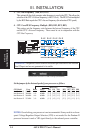
(Board Layout)
III. INSTALLATION