


ASUS P2L97 User’s Manual46
IV. BIOS SOFTWARE
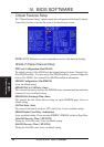
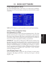
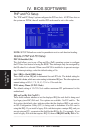
Onboard FDC Swap A & B (No Swap)
This field allows you to reverse the hardware drive letter assignments of your floppy
disk drives. Two options are available: No Swap and Swap AB. If you want to switch
drive letter assignments through the onboard chipset, set this field to Swap AB.
Onboard Serial Port 1 (3F8H/IRQ4)
Settings are 3F8H/IRQ4, 2F8H/IRQ3, 3E8H/IRQ4, 2E8H/IRQ10, and Disabled for
the onboard serial connector.
Onboard Serial Port 2 (2F8H/IRQ3)
Settings are 3F8H/IRQ4, 2F8H/IRQ3, 3E8H/IRQ4, 2E8H/IRQ10, and Disabled for
the onboard serial connector.
Onboard Parallel Port (378H/IRQ7)
This field sets the address of the onboard parallel port connector. You can select
either: 3BCH / IRQ 7, 378H / IRQ 7, 278H / IRQ 5, Disabled. If you install an I/O card
with a parallel port, ensure that there is no conflict in the address assignments. The PC
can support up to three parallel ports as long as there are no conflicts for each port.
Parallel Port Mode (ECP+EPP)
This field allows you to set the operation mode of the parallel port. The setting
Normal, allows normal-speed operation but in one direction only; EPP allows bidi-
rectional parallel port operation at maximum speed; ECP allows the parallel port to
operate in bidirectional mode and at a speed faster than the maximum unidirectional
data transfer rate; ECP+EPP allows normal speed operation in a two-way mode.
ECP DMA Select (3)
This selection is available only if you select ECP or ECP+EPP in the Parallel Port
Mode. Select either DMA Channel 1, 3, or Disable.
UART2 Use Infrared (Disabled)
When enabled, this field activates the onboard infrared feature and sets the second
serial UART to support the infrared module connector on the motherboard. If your
system already has a second serial port connected to the onboard COM2 connector, it
will no longer work if you enable the infrared feature. By default, this field is set to
Disabled, which leaves the second serial port UART to support the COM2 serial port
connector. See IrDA-compliant infrared module connector under section III.
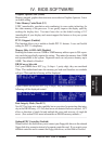
Onboard PCI IDE Enable (Both)
You can select to enable the primary IDE channel, secondary IDE channel, both, or
disable both channels (for systems with only SCSI drives).
IDE Ultra DMA Mode (Auto)
This sets the IDE UltraDMA to be active when using UltraDMA-capable IDE de-
vices. The BIOS will automatically adjust or disable this setting for slower IDE
devices so that Auto or high settings will not cause problems for older IDE devices.
Choose Disable if you do not want this feature for all devices.
IDE 0 Master/Slave PIO/DMA Mode, IDE 1 Master/Slave PIO/DMA Mode (Auto)
Each channel (0 and 1) has both a master and a slave making four IDE devices
possible. Because each IDE device may have a different Mode timing (0, 1, 2, 3, 4),
it is necessary for these to be independent. The default setting of Auto will allow
auto-detection to ensure optimal performance.
IV. BIOS
(Chipset Features)