


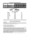


2. CLEARANCES:
Minimum Clearance from Combustible Construction Non-Combustible Construction
Left Side 3" (75mm) 0
Right Side 1" (25mm) 0
Rear 3" (75mm) 2" (51mm)
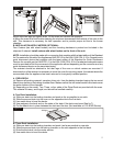
3. SET UP: The oven must be installed in a well-ventilated area.
Your oven is packed standing on its right hand side, opposite to the control side or on its back (Model Y-
800 only). Leave it on its side or its back while unpacking. The skid may be left under the oven for
convenience in further handling. Unpack carefully to avoid damage to the oven. If concealed damage is
found, follow the instructions detailed in Section 1.
Keep the area around the oven free and clear of combustible materials. Do not store any materials on
top of or under any oven. The provision of an adequate air supply to your oven for ventilation and proper
gas combustion is essential. As a minimum, observe the clearances detailed in Section 2. Provide
adequate ventilation and make up air in accordance with local codes.
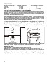
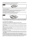
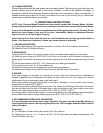
Fit the flue diverter supplied (See fig.1) into the hole located at top near the left rear of the oven and
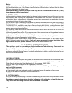
secure with screws for installing the oven under a ventilation hood. For Direct Venting, Optional Draft
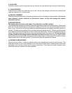
Hood (Fig. 2) must be placed into the hole. Direct Venting not available for European Community
Countries. Local inspectors and ventilation specialists should be consulted to make sure that the
installation of the hood conforms to the local codes and requirements (See fig. 3). In UK ventilation
requirements as detailed in BS 5440 should be followed.
Draft Hood
(For use w/Direct Venting)
Flue Diverter
(For use w/Collection Hood)
B
A
KERS PRIDE
Figure #1
Figure #2
Figure #3
Access to the bottom front door and left side control panel is required for day to day operation of the
oven and for servicing. Make sure that these areas are kept unobstructed for easy access.
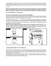
A. MOUNTING LEGS:
Legs are shipped in a separate carton complete with mounting bolts.
a) Bolt two legs to the two upper corners (front) of the oven as it stands on the skid (See fig. 4).
b) Using proper lifting equipment, lower the oven down so that the two bolted legs rest on the floor (See
fig. 5).
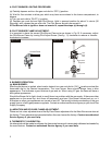
c) Using proper lifting equipment, raise the back side of the oven to a height slightly higher than the
height of the legs, remove the skid and place a sturdy support under the back side (See fig.6).
4