


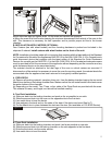
(i) A separate shut-off valve for each oven must be provided. It should be as close as possible to the
place where the gas supply line goes into the oven. It must be located such that it is easily accessible.
(j) When stacking with another oven, two shut-off valves, one for each of the two ovens, must be
provided.
After the Gas Supply has been connected, it is extremely important to check all the piping for
leaks. Use a soap and water solution or a product expressly made for this purpose. Do not use
Matches, Candles or a flame etc to check leaks since these methods are extremely dangerous.
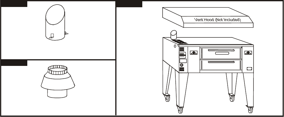
6. FLUE CONNECTION - VENTILATION:
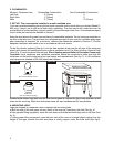
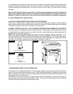
(a) INSTALLATION UNDER VENTILATION HOOD (STANDARD):
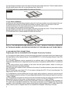
If the oven is installed under a collection hood, use the flue diverter (fig.1) supplied. Local inspectors
and ventilation and environmental specialists should be consulted so that the design and the installation
of the hood conforms to the local / municipal codes (see fig.3).
(b) DIRECT VENTING (Optional) – NOT AVAILABLE FOR EUROPEAN COMMUNITY COUNTRIES:
If direct venting, it is necessary to install a draft hood (fig.2). The flue pipe from the draft hood must not
run downwards at any point from the oven to the final outlet. It should always slant slightly upwards. For
best results it should rise straight up.
NOTE: Do not put a damper in the flue and do not connect a blower directly to the flue. If the
flue runs
directly to the free air outside the building, use a wind deflector or a UL listed vent cap at
the end of the flue pipe. Termination of the vent must be at least 2 feet above the highest part of the
roof within 10 feet (Ref: American Gas Association Catalog No. XH0474).
Draft Hood
(For use w/Direct Venting)
Flue Diverter
(For use w/Collection Hood)
BAKERS PRIDE
Figure #1
Figure #2
Figure #3
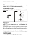
7. MAIN BURNER SAFETY PILOT OPERATION:
The purpose of the safety pilot system is to lock the gas supply to the main burner at the combination
valve, if for any reason the pilot burner is not lit. Oven should be relighted by following the steps given
below. However, in normal service, the pilot flame stays lit indefinitely, day and night or weekends. This
prolongs the life of the safety valve.
The safety pilot valve is in effect a two-stage control. After initial lighting, the pilot burner stays on
without the gas cock dial being held pressed in. After 1-2 minutes, the valve opens fully to let the gas
flow past the safety pilot valve into the burner system.
7