


Installation 1
This machine is designed to be used on either a
wall mount or a fryer mount. This should be
specified when the machine is ordered from the
factory. If the mounting is not specified, the
fryer mount will be shipped.
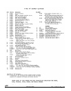
Wall Mount consists of:
Wall Plate #0004
Wall Arm Pin #0011
Set Collar #0121
Arm Bushing #0120
6 Lag Bolts, 5/16-1 ½”
Fryer Mount consists of:
Column, 1 1/8” Dia., #0132-2 (20” Long)
Or #0132-3 (48” Long)
Set Collar #0121
2 Fryer Brackets; #591-16 or #0133
4 Mounting bolts, ¼-20 x 1, NC
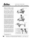
Installation of Wall Mount
It is necessary to provide a good solid support for
mounting the machine to the wall. We suggest
the use of a 2 x 4” timber, securely fastened to
the wall. This 2 x 4 should be long enough to
extend upward from the floor to a distance
approximately 18” higher than the top of the
frying kettle.
If the wall is wood, the 2 x 4 should be securely
spiked to the wall. If the wall is brick, holes
should be drilled, and the 2 x 4 fastened by lag
bolts with expansion bolt shields.
1. Set the frying kettle in position directly in
front or a little to the right of the wall
support, and approximately 6” from the
wall. The Variety Cutter can be mounted
from either side of the kettle or between 2
kettles.
2. Lay a straight edge, (a board will do)
across the kettle top to the 2 x 4.
3. Measure up 9” and mark center which
will be the correct height and position for
the top hole in the wall plate. Drill a ¼”
hole at this point and fasten the wall plate
with the lag screws which come with the
machine.
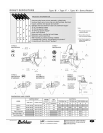
4. Determine the correct vertical position of
the wall plate, then screw the plate down
securely to the 2 x 4 using all 6 screws.
5. To locate the curved arm section in place
on the wall plate, the large bushing
should be installed in the curved arm
section. The set collar should be installed
on the large bushing under the curved
arm. Then slide the ½” pin through the
upper bearing hole on the wall plate,
through the bushing and then through the
lower bearing hole on the wall plate.
Place washer provided on the upright pin
to serve as a thrust bearing. Oil pin
lightly with light machine oil.
6. Set the small straight arm in place on the
pin of the first bracket arm. This should
be also mounted so that the pin is
pointing up. Place ½” washer provided
on the pin. Oil pin lightly with light
machine oil.
7. The donut cutter should be mounted on
the pin of the straight arm. Adjust the set
collar under the curved arm to give the
proper clearance. (A) The guard flange
of the hopper base when mounted on the
machine should just clear the rim of the
Belshaw Bros., Inc. 1750 22
nd
Ave. S. Seattle, WA 98144 Phone 206-322-5474 Fax 206-322-
5425
Donut Cutter Type N MN-1541EN 1