


fryer. (B) The bottom of the cutter
should be 1” to 1 ¼” from the surface of
the shortening.
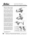
Installation of Fryer Mount
(NOTE: For mounting to 616A or 616”AT
fryers, see instructions for Cut-N-Fry
Combination).
This equipment is designed as a universal unit,
and can be mounted on the corner of most fryers.
The mounting brackets should be mounted on the
back corner on the opposite side of the drain tray.
They can be fastened to the fryer case using ¼”
bolts. Washers and nuts should be used if the
mount is made on the sheet metal case.
1. The brackets should be mounted so as to
be approximately 12” apart if possible.
The upper bracket should be as near the
top of the fryer as possible.
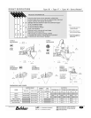
2. After brackets are installed, the mounting
column should be put in place so that it
rests on the surface on which the fryer is
sitting. Then lock with the set screws in
the mounting brackets.
3. Slide set collar into rod (pin up and
toward the back for countertop fryers; pin
down for floor models). Place so that top
of collar is 6” above the rim of the fryer.
This will give approximate location. Oil
rod above set collar lightly with machine
oil.
4. Place bracket arm with large hole on the
rod, sliding down until it rests on the set
collar. This should be set so that the 4”
long pin is pointing up. Place nylon
washer provided on the pin to serve as a
thrust bearing. Oil pin lightly.
5. Set the small straight arm in place on the
pin of the first bracket. This should be
also mounted so that the pin is pointing
up. Place the nylon washer provided on
the pin. Oil lightly with machine oil.
6. The donut cutter should be mounted on
the pin of the outer arm. Adjust the set
collar under the inner arm to give the
proper clearance. (A) The guard flange
of the hopper base, when mounted in the
machine, should just clear the rim of the
fryer. (B) The bottom of the cutter
should be 1” to 1 ¼” from the surface of
the shortening.
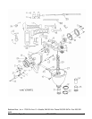
To Assemble the Cutter
1. Position hopper on the small bracket arm
setting mounting hole over the bracket
pin.
2. Insert hopper base in bottom of cylinder,
pushing up to force lock pin out. When
hopper base is fully inserted, rotate until
lock pin goes into place.
3. Position crank case on the double
locating studs. Do not push the crank
case fully into position, holding back
approximately ½”. Start the lock nut on
the end of the threaded locating pin.
4. Insert the plunger by passing rods
through the opening in the hopper center
and having the plunger bearing above the
hopper arch. Lower the plunger bearing
into the bearing seat in the hopper center.
Align the arms with the plunger pins.
When the forks on the trip arms are in
line with the plunger pins, tighten the
crank case locknut which pushes the
crank case into position. Then tighten
lock screw on the hopper center bearing
to hold plunger bearing in place.
Belshaw Bros., Inc. 1750 22
nd
Ave. S. Seattle, WA 98144 Phone 206-322-5474 Fax 206-322-
5425
2 MN-1541EN Donut Cutter Type N