


- 10 -
8. PREPARE THE HOOD (CONT’D)
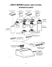
8.1 UP27I SERIES RANGE HOOD (INTERNAL BLOWER) (CONT’D)
H
ORIZONTAL DISCHARGE (DUCTED INSTALLATION ONLY)(CONT’D)
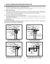
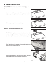
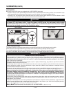
Using 3 no. 8 x 3/8” screws provided with hood, secure the adapter/damper
on the back of the hood. Remove tape from damper flap.
Seal the adapter/damper and the metal shut-off plate to the hood using
duct tape.
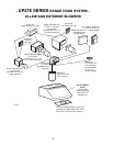
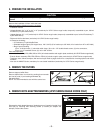
8.2 UP27E SERIES RANGE HOOD (EXTERIOR OR IN-LINE BLOWER)
HD0204
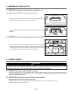
Run house wiring (120 V AC) to installation location. Refer to the instructions
included with the selected blower/rough-in kit (sold separately) for details
on installing the rough-in plate. Install the rough-in plate so that the wiring
box is located on the right side as you are facing the hood.
HD0210
ROUGH-IN PLATE
ON TOP OF HOOD
LOCKNUTS
WIRING COVER
HD0205
ADAPTER/DAMPER
SCREW LOCATION
TOP OF HOOD
BACK OF HOOD
WARNING
Risk of electrical shock. Electrical wiring must be done by qualified personnel in accordance with all
applicable codes and standards. Before connecting wires, switch power off at service panel and lock
service disconnecting means to prevent power to be switched on accidentally.
!
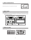
9.1 UP27I SERIES RANGE HOOD (INTERNAL BLOWER)
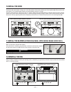
Run house wiring (120 V AC) to installation location. Place the electrical cable clamp, insert the cable in the hood and
tighten the electrical cable clamp to secure the cable. Connect BLACK to BLACK, WHITE to WHITE and GREEN or bare
wire under GREEN ground screw.
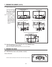
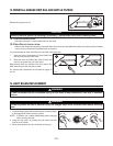
9.2 UP27E SERIES RANGE HOOD (EXTERIOR OR IN-LINE BLOWER)
Remove wiring cover from rough-in plate and set aside.
Connect BLACK to BLACK, WHITE to WHITE and GREEN or bare wire under GREEN ground screw.
Reinstall wiring cover on rough-in plate.
9. CONNECT WIRING