


6
TECHNICAL INFORMATION FOR THE
INSTALLER
This appliance shall be installed only by authorised
personnel and in accordance with the manufacturer’s
installation instructions, local gas fitting regulations,
municipal building codes, water supply regulations,
electrical wiring regulations, AS 5601/AG 601 – Gas
Installations and any other statutory regulations.
3) INSTALLING THE HOT PLATE
Check that the appliance is in a good condition after
having removed the outer packaging and internal
wrappings from around the various loose parts. In
case of doubt, do not use the appliance and contact
qualified personnel.
Never leave the packaging materials (cardboard,
bags, polystyrene foam, nails, etc.) within
children’s reach since they could become
potential sources of danger.
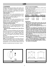
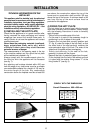
The measurements of the opening made in the top
of the modular cabinet and into which the hot plate
will be installed are indicated in fig. 7.
Always comply with the measurements given for
the hole into wich the appliance will be recessed
(see fig. 7).
Any adjoining wall surface situated within 200 mm
from the edge of any hob burner must be a suitable
non-combustible material for a height of 150 mm for
the entire length of the hob. Any combustible
construction above the hotplate must be at least 600
mm above the construction above the top of the
burner and no construction shall be within 450 mm
above the top of the burner. A minimum depth of 60
mm from the top of the work surface must be
provided for this appliance.
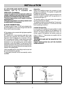
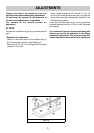
4) FIXING THE HOT PLATE
The hot plate has a special seal which prevents
liquid from infiltrating into the cabinet. Strictly comply
with the following instructions in order to correctly
apply this seal:
- Take off all the movable parts of the hob.
- Cut the seal in 4 parts of the necessary length to
positioning it on the 4 edges of the crystal.
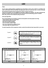
- Overturn the hot plate and correctly position seal
“E” (fig. 8) under the edge of the hob itself, so that
the outer side of the seal perfectly matches the
outer perimetral edge of the hob. The ends of the
strips must fit together without overlapping.
- Evenly and securely fix the seal to the hob,
pressing it in place with the fingers.
- Remove the strip of protective paper from the seal.
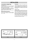
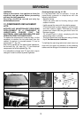
Fit the hot plate into the hole in the cabinet and lock
it in place with the relative fixing screws “F” of the
fixing hooks “G” (see fig. 9).
INSTALLATION
FIG. 8 FIG. 9
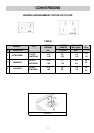
FIG. 7
COMPLY WITH THE DIMENSIONS
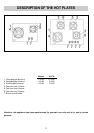
Overall Dimensions: 680 x 500 mm
AB
2B 480 328
4B 645 470