


8
INSTALLATION
1. Uncrate carefully. Report any hidden freight damage to the freight company immediately.
2. Ideally an exhaust system should be directly above the appliance to exhaust combustion
gases generated by the unit.
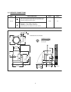
3. The appliance is intended for use on noncombustible floors. The minimum clearance from
combustible and noncombustible floor construction is 0" on right side, 0" on left side and 6"
(152 mm) from the back of the flue chimney.
4. Appliance location must allow air supply to unit and obstruction free clearance for air opening
into the combustion chamber.
5. Set the appliance in place and level using spirit level. Level left to right and front to back.
6. Mark hole locations on the floor through the anchoring holes provided in the flanged adjustable
feet.
7. Remove the appliance from installation position and drill holes in locations marked on the floor.
(See installation diagram on Page 4). Insert proper anchoring devices. (Not supplied).
8. Place appliance back in the installation position and re-level left to right and front to back.
9. Bolt and anchor appliance securely to the floor.
10. Seal bolts and flanged feet with silastic or equivalent compound.
11. Make service connections as indicated.
12. The pressure relief valve is located at the left rear of the unit. This area should be kept clear
and should not be in an area where operators will normally stand. The elbow on the relief
valve should be turned toward the floor. 3/4" diameter pipe may be used to extend to the floor,
but must not be piped directly to a drain. It must be vented to the atmosphere.
13. Check the pressure gauge on the front panel before operating. The reading should be in the
green vacuum zone (below 0 PSI). See “Re-establishing Vacuum” section under Service
Instructions.