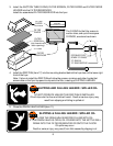
D. ELECTRICAL INSTALLATION
1. Refer to the nameplate on the front of the fryer. Verify the ELECTRICAL SERVICE POWER.
Voltage and phase must match the nameplate specifications, and available electrical service
amperage must meet or exceed the specifications listed on page 1.
Wiring must be no less than12 ga. solid copper wire, rated for at least 75ºC.
NOTE: Wire gauge, insulation type and temperature rating , as well as type, size and
construction of conduit, must meet or exceed applicable specifications of local codes and
of the National Electrical Code.
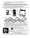
2. Fryers are shipped from the factory wired for 3Ø electrical service. Refer to theThree-Phase
Wiring Diagram included with this fryer, and verify that field wiring conforms to this diagram .
NOTE: FRYERS are FIELD CONVERTIBLE to 1Ø. If single-phase operation is required,
refer to the 3-phase to 1-phase Instructions included with the FRYER, and verify that both
internal wiring and field wiring conform to the included single-phase wiring diagram .
DANGER
ELECTRICAL SHOCK HAZARD
ELECTRICAL CONNECTIONS MUST BE MADE BY A LICENSED
ELECTRICIAN
Electrical shock will cause death or serious injury.
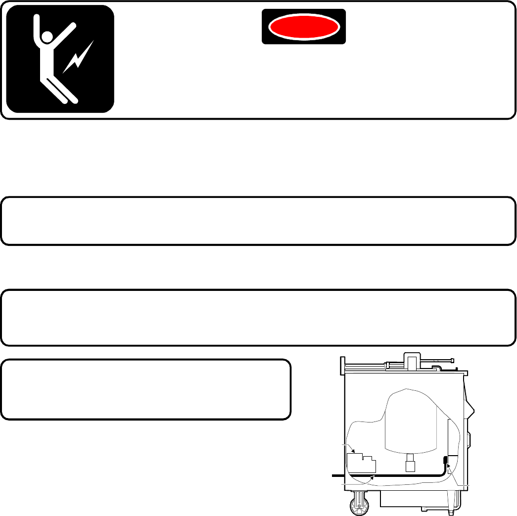
POWER
CORD
FRYPOT
90º
CONDUIT
FITTING
FILTER
PUMP &
MOTOR
6
IMPORTANT: Field wiring must be routed and
secured away from the FRYPOT, TUBING
and FILTER PUMP AND MOTOR.
C. EQUIPMENT SET-UP
1. Setup the FRYER only on a firm, level, non-combustable surface. Verify local codes for
requirements. Concrete, tile, terrazzo or metal surfaces are recommended. Metal over
combustible material may not meet code for non-combustible surfaces.
2. LEVELING: Verify that the fryer sits firmly ON BOTH CASTERS AND ON BOTH LEGS.
With a spirit level, check that the fryer is level front-to-back and side-to-side. With the
adjustable legs, adjust as required to level the fryer.
NOTE: Field wiring must allow access to the
rear of the FRYER for cleaning and for access
to the oil filter pump motor RESET BUTTON.


