


H
67
Heater Assembly
Fig. 16-11 Fig. 16-12
1
2
3
4
6
7
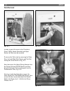
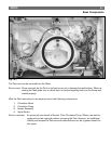
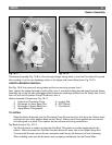
The Heater Assembly, Fig. 16-8 is a flow through design, taking water in from the Circulation Pump and
then sending it out the two discharge outlets to the Upper and Lower Spray Arms, Fig. 16-10.
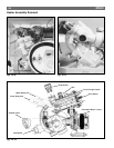
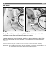
HEATER ASSEMBLY REMOVAL:
See Fig. 16-9, first remove all wiring leads and the two securing screws, item 1.
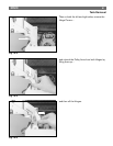
Now, release the Heater Assembly Locking Tab, item 2, and while holding the tab open bring the Heater
Assembly up on the left side, disengaging the heaters two discharge outlets from the Sump, item 3, and
then out from the Circulation Pump Connection, item 4.
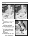
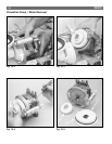
Heater Assembly Components, Fig. 16-11.
1. Intake from Circulation Pump. 5. Locking Tab
2. Discharge to Lower Spray Arm. 6. NTC Socket
3. Discharge to Upper Spray Arm. 7. Flow Switch
4. Aqua Sensor (if equipped).
TO INSTALL:
Slide the Heater Assembly into the Circulation Pump Connection first, then bring the Heater down
and seat the two outlet gaskets back into the Sump. Make sure all three gaskets are secure and
the locking tab is in place. Then replace the two screws and wiring connections.
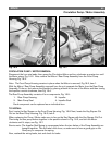
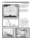
Top Rack Actuator, Fig. 16-12.
Top Rack Actuator is used to activate the Top Rack Only wash on models equipped with this
feature. When activated, the Top Rack Actuator diverts all water flow to the Upper Spray Arm.
To remove the Actuator, remove the wire connector, and then pry the Actuator out from its housing.
When installing, make sure the Actuator’s arm is properly inserted back into the Control Gate.
5