


15
Step 4: Install Ductwork (Remote
Blower, If Used)
A. Install the ductwork and remote blower
(if used) in accordance with the ductwork
routing plan developed in Step 1.
B. Make sure that the installation complies
with all installations guidelines. Also
check that the opening where duct
passes through outside wall or roof has
been properly flashed and sealed to
prevent leakage.
C. If using Integral Blower, Model
DHG601DUC, proceed to Step 5.
D. If using Remote Blower Model
DHG6015DUC or DHG6023UC, refer to
Installation Instructions with that model.
Step 5: Install Electrical Service
Check your local building codes for proper
method of installation. In the U.S., if there
are no applicable local codes, this unit
should be installed in accordance with the
National Electric Code ANSI/NFPA No. 70,
Current Issue. (In Canada, installation must
be in accordance with the CAN 1-B149.1
and .2-Installation Codes for Gas Burning
Appliances and/or lodal codes).
The appliance must be grounded. In the
event of an electrical short circuit,
grounding reduces the risk of electric shock
by providing an escape wire for the
electric current. This appliance is
equipped with a cord having a grounding
wire with a grounding plug. The plug must
be plugged into an outlet that is properly
installed and grounded.
WARNING – Improper grounding can result
in a risk of electric shock.
Consult a qualified electrician if the
grounding instructions are not completely
understood, or if doubt exists as to whether
the appliance is properly grounded.
Do not use an extension cord. If the power
supply cord is too short, have a qualified
electrician install an outlet near the
appliance.
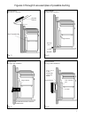
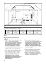
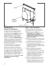
The receptacle should be located under the
countertop so that the 30 inch long power
cord from the vent will reach it.
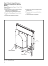
See Figure 9. The cord should be routed
beneath the appliance and away from heat
generated by the cooktop. Access should
not be obstructed by blower, cabinet work,
ductwork or electrical/gas utilities for the
cooktop. All power for the vent system
(including the remote blower, if used) is
supplied via the cord to the intake unit. The
outlet can usually be extended from another
kitchen outlet or have its own circuit from
the main service panel.
Do not plug vent cord into receptacle until
Step 8.
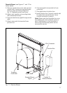
Step 6: Mount Vent and Cooktop
A. Remove grease filters and any packing
materials from inside the intake.
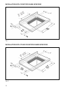
B. Set the vent intake into rear of
countertop opening. Carefully lower it
into position so that the flanges on the
rear sides and edges fully support the
unit hanging from the coluntertop.
C. Hold the unit against the rear of the
countertop opening, and slide the leg
brackets down to meet the bottom of
cabinet. Check and adjust for plumb,
then fasten leg brackets to cabinet with
hardware provided.
D. Place the cooktop in countertop opening
with the rear edge of cooktop
overlapping the front edge of the vent.
Make sure rear edge of cooktop does
not bind against front of snorkel.
Follow the manufacturer’s installation
instructions for installing gasket strips,
protective heat tape (if required),
securing the cooktop to the countertop
and making the cooktop electrical and/or
gas connections.