


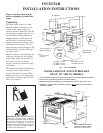
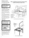
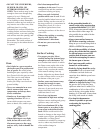
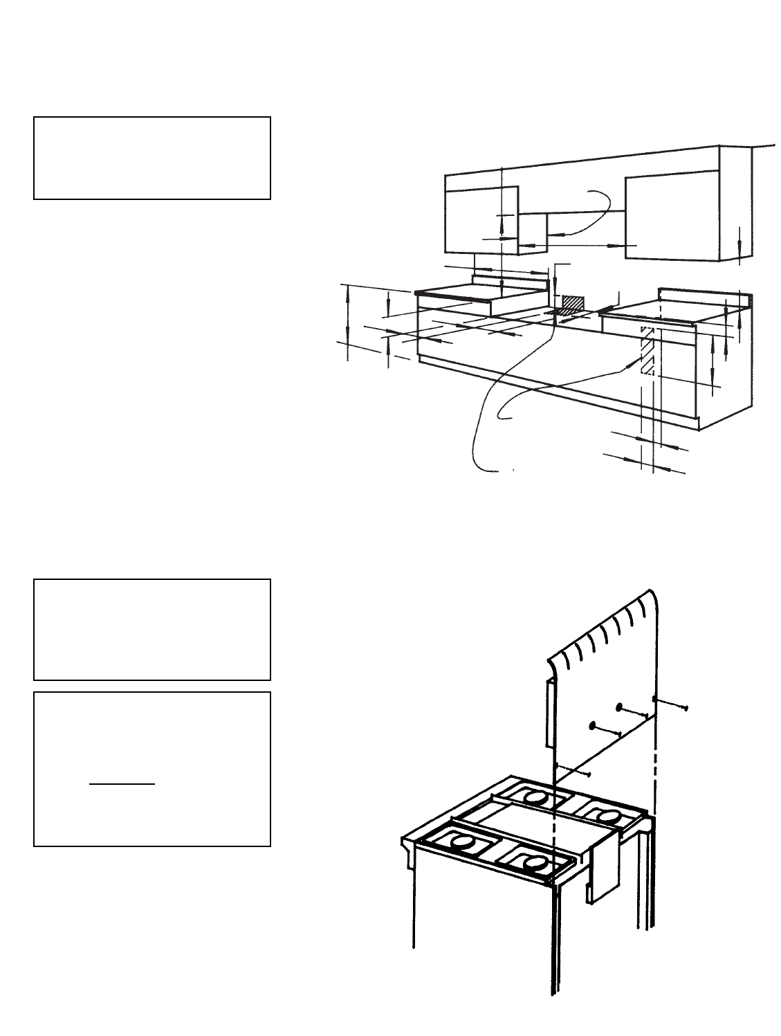
Backguard Assembly
The backguard, located in the “top
pack” of the range, must be installed
prior to placing the range in position
for gas hookup. See Figure 7.
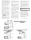
Positioning/Leveling
To position the range use a lift jack or
enough manpower to lift the range
completely. Avoid sliding, pushing, or
pulling the range because this
increases the possibility of bending
the legs or the coupling connectors
and could also result in damage to the
floor covering.
Ranges and built-in cooktops must be
level to obtain proper cooking results.
Ranges adjust from 35
7
/8” to 37
7
/8” or
2” max. All units must be level front-
to-back and side-to-side. See Fig. 2.
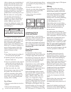
Built-in cooktops must be installed in
a cut-out and on a level surface, as
illustrated in Fig. 6.
NEVER BLOCK THE FLOW
OF AIR FOR COMBUSTION
OR VENTILATION. SEE
INSTRUCTION FIG. 2.
Adjustments
Appliances will either be set for use
with Natural gas or Propane (LP) gas.
The factory orifice setting is indicated
by a second alpha prefix letter in the
model number. The letter “T”
indicates a natural gas setting. The
letter “P” indicates a propane (LP)
setting.
ALL ADJUSTMENTS AND/OR
CONVERSIONS MUST BE
MADE BY THE INSTALLER
OR SERVICING UTILITY
DURING INSTALLATION.
SEALED TOP BURNER
MODELS ARE FACTORY SET
FOR THE GAS FOR WHICH
THEY ARE TO BE USED.
THEY CANNO
T BE CHANGED
FROM ONE GAS TO
ANOTHER WITHOUT
FACTORY AUTHORIZATION.
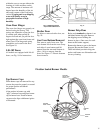
FIG. 6 COOKTOP INSTALLATION CLEARANCES
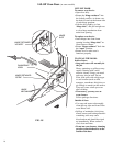
FIG. 7 BACKGUARD INSTALLATION
NOTE: COOKTOPS DO NOT HAVE LEVELING LEGS.
CABINET SUPPORT MUST BE LEVEL.
6
40” MINIMUM
13”
MAXIMUM
WIDTH OF
RANGE
6” MINIMUM
18” MINIMUM
2”
2”
2”
1 1/2”
36”
6 3/16”
2”
12”
2 1/2”
5 1/2”
CUT-OUT WIDTH
48” COOKTOP = 48 3/16”
36” COOKTOP = 36 3/16”
CUT-OUT HEIGHT
6 3/16” including
countertop thickness
24” DEEP BASE CABINETS
SUGGESTED
NOTE:
FASTENERS ARE
PROVIDED AND MUST
BE REMOVED
AND RE-USED
AMOUNT PROVIDED:
30” - 4
36” - 4
48” - 5
60” - 6
ELECTRICAL
CONNECTION
AREA
GAS CONNECTION
AREA