


Page 16
SERVICE (cont.)
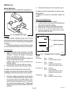
Warmer Switch(es)
RL: Left Rear, Left Front, Right Rear & Right Front
WARNING
!
H
I
G
H
H
E
A
T
W
A
R
M
E
R
DO
NO
T
B
O
I
L
DEC
AN
TER
D
R
Y
K
EE
P
C
O
M
B
UST
IBL
ES
A
WAY
FAI
L
U
RE
T
O
C
O
M
P
L
Y
R
IS
K
S
G
L
A
SS F
AI
L
UR
E/H
O
T
LI
Q
UID
B
UR
NS
AND
F
IRE
HA
Z
ARD
CAUTION
D
I
S
C
A
R
D
D
E
C
A
N
T
E
R
I
F
:
.
C
R
A
C
K
E
D
.
S
C
R
A
T
C
H
E
D
.
B
O
I
L
E
D
D
R
Y
.
H
E
A
T
E
D
W
H
E
N
E
M
P
T
Y
.
U
S
E
D
O
N
H
I
G
H
F
L
A
M
E
.
O
R
E
X
P
O
S
E
D
E
L
E
C
T
R
I
C
E
L
E
M
E
N
T
S
F
A
I
L
U
R
E
T
O
C
O
M
P
L
Y
R
I
S
K
S
IN
J
U
R
Y
P
N
:
6
58
1
9
8
5
B
U
N
N
-
O
-
M
A
T
IC
C
O
R
P
O
R
A
T
I
O
N
F
U
N
N
E
L
C
O
N
T
E
N
T
S
A
R
E
H
O
T
!
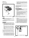
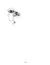
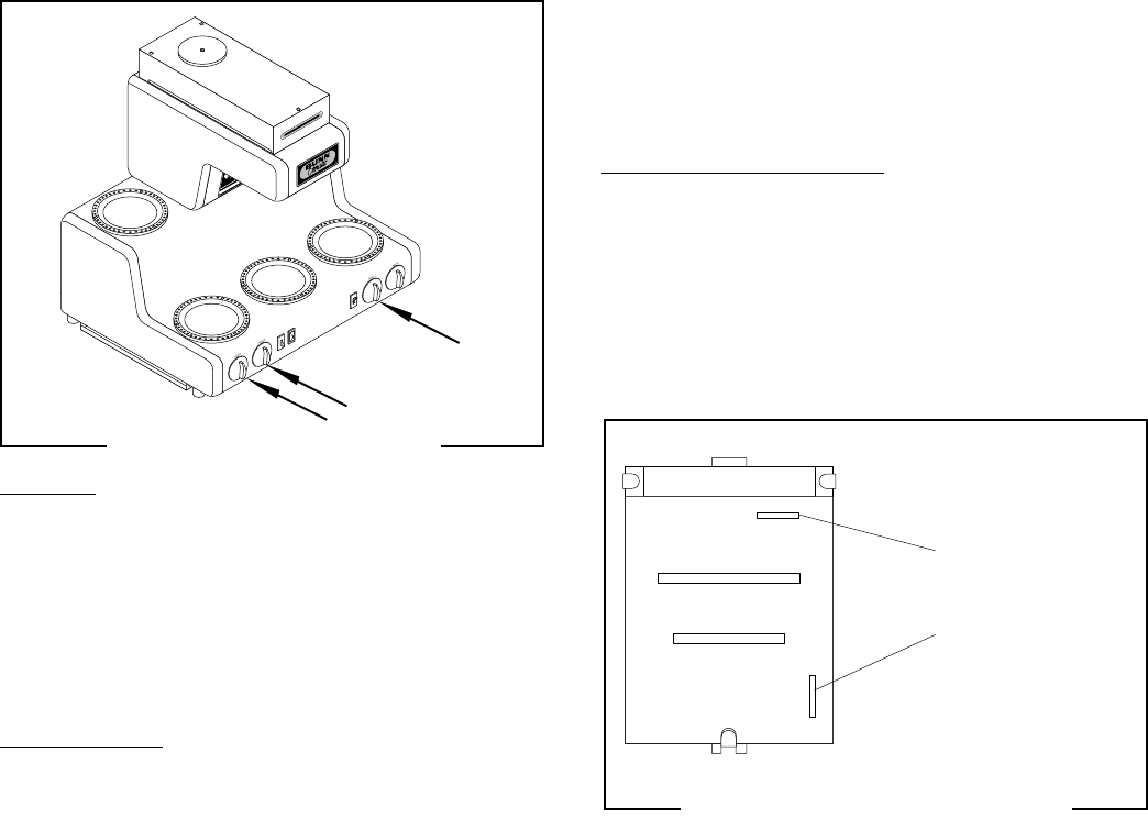
FIG. 10 WARMER SWITCHES
Location:
These warmer switches are the two at the left
and the left most one on the right of the base as viewed
from the front, FIG. 10. Their knobs are marked Off/
On/Off/On.
To test these switches, access will also be needed
to the terminal block located in the rear of the brewer.
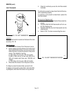
Test Procedure:
1. Check the voltage across terminal L1 and the
white or red wire on the terminal block with a
voltmeter. Connect the brewer to the power
source. The indication must be:
a) 120 volts ac for two wire 120 volt models and
three wire 120/240 volt models.
b) 200 or 240 volts ac for two wire 200 volt or
240 volt models.
c) 100 volts ac for two wire 100 volt models.
2. Disconnect the brewer from the power source.
If voltage is present as described, proceed to #3.
If voltage is not present as described, refer to the Wir-
ing Diagrams and check the brewer wiring harness.
3. Check the voltage across terminal 1 and the white
or red wire on the terminal block with a voltme-
ter when the switch is in the "ON" position. Con-
nect the brewer to the power source. The indica-
tion must be as described in step 1. Voltage must
not be present across these terminals in the "OFF"
positions.
4. Disconnect the brewer from the power source.
If voltage is present as described, the switch is oper-
ating properly.
If voltage is not present as described, replace the
switch.
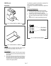
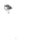
Removal and Replacement:
1. Remove the knob from the switch.
2. Loosen the 5/8" nut on the switch shaft and push
the switch through the opening.
3. Remove the wires from the switch terminals.
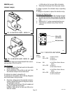
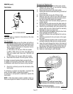
4. Refer to FIG. 11 when reconnecting the wires.
5. Securely mount the new switch onto the hous-
ing and reinstall the knob.
MODEL
RL Left Rear BLK 1 to Warmer
BLK L1 to Left Front Warmer Switch
RL Left Front BLK 1 to Warmer
BLK L1 to Left Rear Warmer Switch
to Brew Station Warmer Switch
RL Right Front BLK 1 to Warmer
BLK L1 to Terminal Block
to Brew Station Warmer Switch
to Right Rear Warmer Switch
RL Right Rear BLK 1 to Warmer
BLK L1 to Right Front Warmer Switch
L1
1
BLK (L1) (see below)
BLK (1) (see below)
P1713
P1695
FIG. 11 WARMER SWITCH WIRING
32430 121699