


Page 20
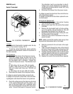
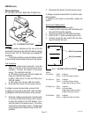
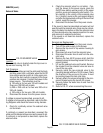
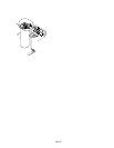
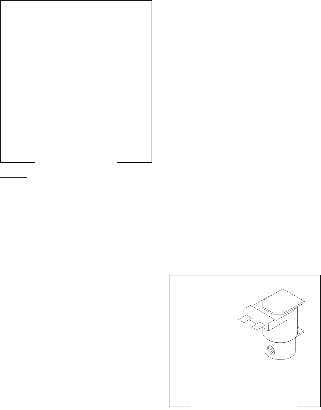
FIG. 20 SOLENOID VALVE
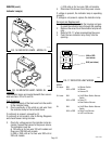
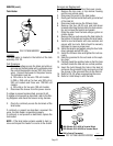
FIG. 21 SOLENOID VALVE WIRING
SERVICE (cont.)
Solenoid Valve
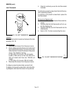
4. Check the solenoid valve for coil action. Con-
nect the brewer to the power source, place the
On/Off brew station warmer switch in the upper
position, press and release the start switch. Lis-
ten carefully in the vicinity of the solenoid valve
for a "clicking" sound as the coil magnet attracts
and after the approximate setting of the level float
switch, repels the plunger.
5. Disconnect the brewer from the power source.
If the sound is heard as described and water will not
pass through the solenoid valve, there may be a block-
age in the water line before or after the solenoid valve
or, the solenoid valve may require inspection for wear,
and removal of waterborne particles.
If the sound is not heard as described, replace the
solenoid valve.
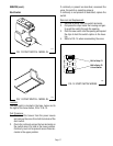
Removal and Replacement:
1. Disconnect the brewer from the power source.
2. Turn off the water supply to the brewer.
3. Remove the top cover or top warmer housing to
gain access.
4. Disconnect all wires from the solenoid valve.
5. Disconnect the water lines to and from the sole-
noid valve.
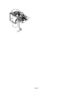
6. Remove the two #8-32 screws which hold the
solenoid valve and mounting bracket to the com-
ponent bracket.
7. Lift out the solenoid valve and bracket. Remove
the bracket from the solenoid valve and save to
mount the new valve.
8. Securely install the new solenoid valve to the
mounting bracket with two #10-32 screws. Check
the direction of flow arrow on the valve. It must
be pointing toward the tank inlet tube.
9. Securely attach the valve and bracket to the com-
ponent bracket using the two #8-32 screws.
10. Securely fasten the water lines to and from the
solenoid valve.
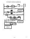
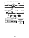
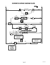
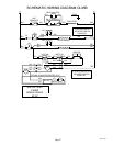
11. Refer to FIG. 21 when reconnecting the wires.
Location:
The solenoid valve is located under the top cover or
top warmer housing, FIG. 20.
Test Procedure:
1. Check the voltage across the white and the black
and blue wires with a voltmeter when the On/Off
brew station warmer switch is in the upper posi-
tion and the start switch is pressed to the lower
position and released. Connect the brewer to the
power source. The indication must be:
a) 120 volts ac for two wire 120 volt models and
three wire 120/240 volt models,
b) 200 or 240 volts ac for two wire 200 volt or
240 volt models,
c) 100 volts ac for two wire 100 volt models.
2. Disconnect the brewer from the power source.
If voltage is present as described, proceed to #3.
If voltage is not present as described, refer to the Wir-
ing Diagrams and check the brewer wiring harness.
3. Check for continuity across the solenoid valve
coil terminals.
If continuity is present as described, reconnect the
white and the black and blue wires and proceed to #4.
If continuity is not present as described, replace the
solenoid valve.