Page 11
TROUBLESHOOTING
A troubleshooting guide is provided to suggest probable causes and remedies for the most likely problems
encountered. If the problem remains after exhausting the troubleshooting steps, contact the Bunn-O-Matic
Technical Service Department.
• Inspection, testing, and repair of electrical equipment should be performed only by qualified service personnel.
• All electronic components have 120 volt ac and low voltage dc potential on their terminals. Shorting of
terminals or the application of external voltages may result in board failure.
• Intermittent operation of electronic circuit boards is unlikely. Board failure will normally be permanent. If an
intermittent condition is encountered, the cause will likely be a switch contact or a loose connection at a
terminal or crimp.
• Solenoid removal requires interrupting the water supply to the valve. Damage may result if solenoids are
energized for more than ten minutes without a supply of water.
• The use of two wrenches is recommended whenever plumbing fittings are tightened or loosened. This will help
to avoid twists and kinks in the tubing.
• Make certain that all plumbing connections are sealed and electrical connections tight and isolated.
• This brewer is heated at all times. Keep away from combustibles.
WARNING –•Exercise extreme caution when servicing electrical equipment.
• Unplug the brewer when servicing, except when electrical tests are specified.
• Follow recommended service procedures.
• Replace all protective shields or safety notices.
Before troubleshooting this brewer, check for the following:
A. Control Boards (CDBC)
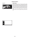
1. Make sure ribbon cable is properly attached to the control board (ALL PINS INSERTED INTO PLUG).
2. Make sure there is a nylon insulating washer under each screw head that holds the control board to the plastic
front end cap. This is important for proper operation.
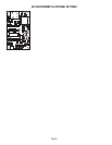
B. Control Boards (CEZ)
Locate J6 connector on control board. If jumper is across pins 1 & 2, board is set up to operate tea brewer or
a brewer that DOES NOT use a water level probe. If jumper is across pins 2 & 3, board is set up to operate a
coffee brewer or a brewer that uses a water level probe. Look at the bottom side of the control board. Pin 1 of
connector J6 is marked by a square solder pad on the foil side of the board and pins 2,3 & 4 are marked by a
round solder pad.
C. Control Boards (CDBC & CEZ)
Make sure before servicing brewer that voltage is present at control board.
On CDBC models, press any warmer switch or observe if any indicator lights are glowing on the control panel.
If so, proceed with testing. If not, check for voltage across pins 1 & 2 of the ten pin J1 connector (black and
white wires). If voltage is present, replace the control board. If voltage is not present, check wiring and voltage
across terminal block (black and white). Correct the problem and retest before proceeding with testing.
On CEZ models, check for voltage across pins 1 & 7 of the eight pin J1 connector (black and white wires). If
voltage is present, proceed with testing. If voltage is not present, check wiring and voltage across terminal block
(black and white). Correct the problem and retest before proceeding with testing.
29079 042803


