


15
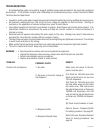
J4
J1
J2
J3
J4
J1
J2
J3
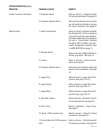
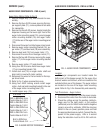
SERVICE (cont.)
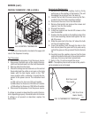
RED to BRN/WHI from
Control Board #1 J3-3
RED to WHI/RED from
Control Board #1 J3-2
RED to WHI/ORN from
Control Board #1 J3-1
RED to WHI/YEL from
Control Board #2 J3-3
BLK to GRN from
Control Board J3-4
P1639
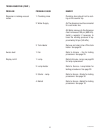
FIG. 3 AUGER MOTOR TERMINALS
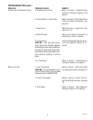
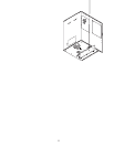
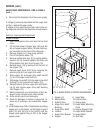
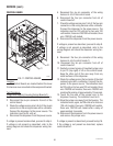
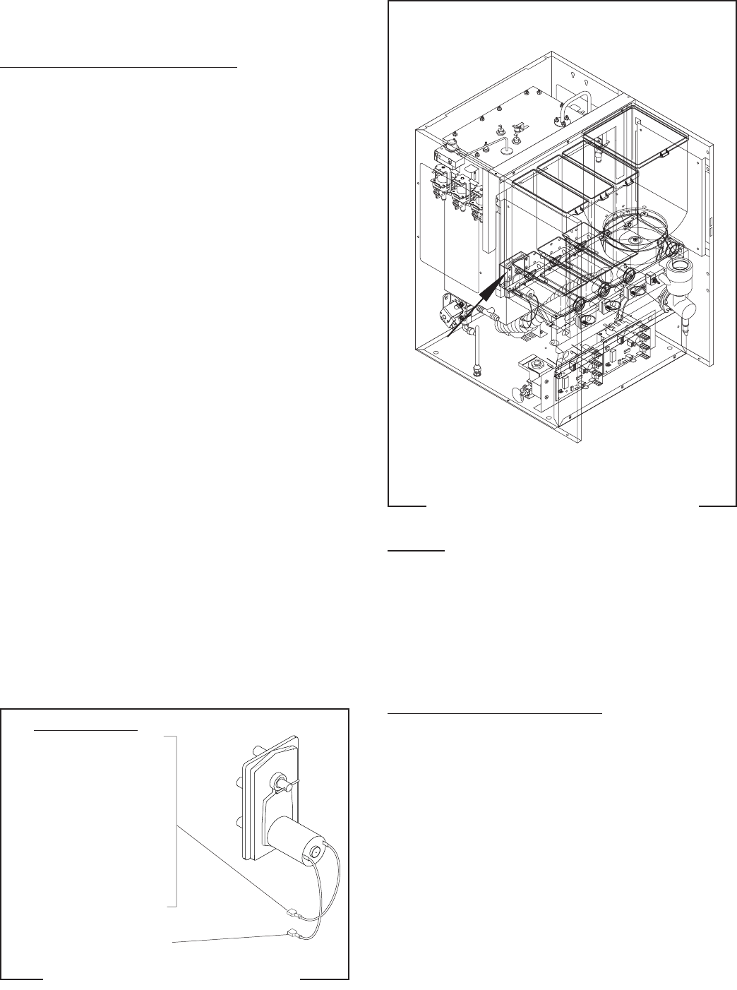
FIG. 4 AUGER DRIVE COMPONENTS
Location
The auger components are located inside the
bottom part of the hopper except for the auger drive
bracket, washer and locknut, which are located on the
outside bottom rear of the hopper. The auger motors
are located on the rear of the auger motor mounting
panel. Refer to Fig. 5 for disassembly and assembly.
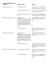
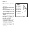
Test Procedures - Auger motors
1. Disconnect the dispenser from the power source.
2. Disconnect the wires from the motor to be tested.
3. Check the voltage across the positive (white/or-
ange) wire for the right motor, or the positive
(white/red) wire for the left motor and the negative
(green) wire with a voltmeter. With the rinse/run
switch in the run (lower) position press and hold
the appropriate dispense switch. Connect the dis-
penser to the power supply. After a .6 second
delay the indication must be 4.0 to 24.5 volts dc.
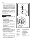
AUGER DRIVE COMPONENTS - FMD-4 & FMD-5
P2635
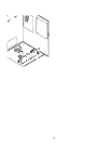
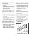
AUGER DRIVE COMPONENTS - FMD-4 (cont.)
Auger Drive Motor (Refer to Fig. 2)
1. Remove hopper assy (15), and set aside for reas-
sembly.
2. Remove the four #8-32 screws securing the hop-
per support plate (11), remove plate and set aside
for reassembly.
3. Remove the four #8-32 screws, located inside the
dispenser housing on the lower right front of the
auger motor mounting panel (19), securing auger
motor mounting bracket (16) and auger motor
(17) to the rear of the auger motor mounting panel
(19).
4. Disconnect the wires from the hopper drive board.
5. Remove auger motor mounting bracket (16), au-
ger motor (17) and dust seal (18) as an assembly.
6. Remove dust seal (18) from auger motor (17).
7. Disconnect the wires from the auger motor (17).
8. Remove the four #8-32 screws securing the auger
motor (17) to the auger motor mounting bracket
(16).
9. Remove auger motor (17) and discard.
10. Using four #8-32 screws install new auger motor
(17) on mounting bracket (16).
11. Install dust seal (18) on auger motor shaft and
align notch in seal with motor casting.
12. Reconnect the wires to the terminals on the hop-
per drive board.
13. Refer to Fig. 3 when reconnecting wires.
14. Using four #8-32 locking screws install auger
motor, dust seal and mounting bracket to the rear
of the auger motor mounting panel (19).
15. Install hopper assy (15).
STATIONS 1 - 4
35135 012103