


20
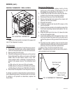
J4
J1
J2
J3
J4
J1
J2
J3
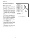
5. Reconnect the six pin connector of the wiring
harness to J3 of the control board.
6. Disconnect the four pin connector from J4 of
control board #1.
7. Check the voltage across pins 1 & 4 of the four pin
connector on the wiring harness with a voltmeter.
Connect the dispenser to the power source. The
indication must be 120 volts ac for two wire 120
volt models, three wire 120/208 volt models, three
wire 120/240 volt models.
8. Disconnect the dispenser from the power source.
If voltage is present as described, proceed to step 9.
If voltage is not present as described, refer to the
wiring diagram and check the dispenser wiring har-
ness.
9. Reconnect the four pin connector of the wiring
harness to J4 of control board #1.
10. Disconnect the ten pin connector from J2 of
control board #1.
11. Carefully connect a piece of insulated jumper wire
to pin 10 (top right) of J2 on the control board.
Keep the other end of this wire away from any
metal surfaces of the dispenser.
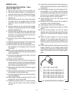
12. Check the voltage across the terminals of the inlet
solenoid valve with a voltmeter. Connect the dis-
penser to the power source. The indication must
be 120 volts ac for two wire 120 volt models, three
wire 120/208 volt models, three wire 120/240 volt
models after a delay of approximately 10 seconds.
13. Touch the free end of the jumper wire to the
dispenser housing. The indication must be 0.
14. Move the jumper wire away from the housing. The
indication must, again, be 120 volts ac for two wire
120 volt models, three wire 120/208 volt models,
three wire 120/240 volt models after a delay of
approximately 5 seconds.
15. Disconnect the dispenser from the power source
and remove the jumper wire.
If voltage is present as described, proceed to step 16.
If the voltage is not present as described, replace
control board #1.
SERVICE (cont.)
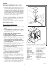
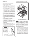
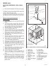
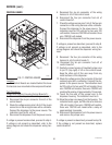
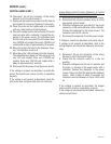
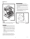
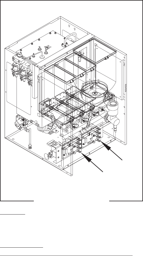
CONTROL BOARD
FIG. 11 CONTROL BOARD
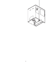
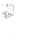
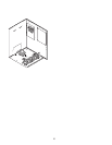
Location:
The Control Boards are located behind the lower
front access cover mounted on the component bracket.
Test Procedure:
Liquid Level Control Circuitry(Control Board #1):
1. Disconnect the dispenser from the power source.
2. Disconnect the six pin connector from J3 of the
control board.
3. Check the voltage across pins 5 & 6 of the six pin
connector on the wiring harness with a voltmeter.
Connect the dispenser to the power source. The
indication must be 24 volts ac.
4. Disconnect the dispenser from the power source.
If voltage is present as described, proceed to step 5.
If voltage is not present as described, refer to the
wiring diagram and check the dispenser wiring har-
ness.
P2635
#1
#2
35135 012103