11
SERVICE (cont,)
AC MOTOR AND GRIND CHAMBER (cont.)
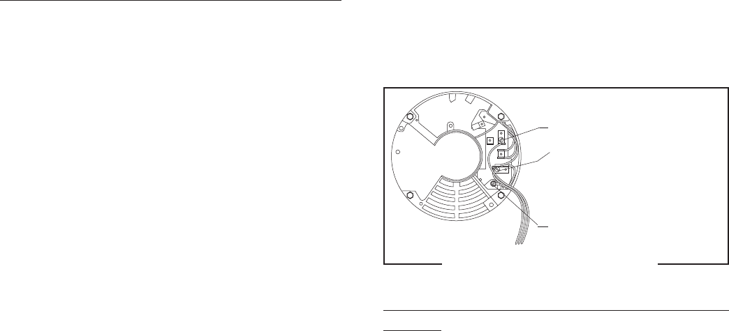
WHI/BLU to
Relay N.O.(K4)
WHI to Cordset (120V)
RED/BLK to Cordset (230V)
GRN to Ground (120V)
GRN/YEL to Ground (230V)
P1310
Removal and Replacement - Grind Chamber - Refer
to Fig. 6:
1. Loosen the two set screws (16) securing the grind
selector knob to the grind selector dial plate (18)
and remove knob.
2. Remove the adjusting screw w/bearing (19).
Inspect adjusting screw w/bearing for wear.
Replace if excessively worn or damaged.
FIG. 5 AC MOTOR TERMINALS
11. Clean all grinding burrs and mounting surfaces
before reassembly.
12. Install the four .250”-20 cage nuts on the new
motor.
13. Place the new motor with hopper collar and bush-
ing into position on the bushings on the motor
mounting bracket.
14. Using four .250”-20 screws, flat washers and
rubber washers secure the motor to the mounting
bracket.
15. Install stationary burr (9) to the grind chamber
housing using two .250”-20 screws.
16. Install burr (7) and burr auger rotor/spring as-
sembly (3) on to motor shaft.
17. Install motor shaft extension (11) on motor
shaft.
18. Align the slot in the motor shaft extension (11)
with the slot in the burr auger rotor/spring as-
sembly (6) and install shear plate (4).
19. Install burr rotor cup (5).
20. Install grind selector dial plate and grind selector
knob assembly on the grind chamber housing and
secure with two .250”-20 screws.
21. Refer to Fig. 5 and reconnect the wires.
22. Refer to ADJUSTMENTS on page 5 and reset the
burrs.
4. Check the voltage across the white, red or red/
black and white/blue wires on terminals L1 &
L2 with a voltmeter. Connect the grinder to the
power source. When the Off/On/Start switch is
momentarily placed in the “START” (lower) posi-
tion and then left in the “ON” (center) position
and a bag is in place behind the coffee dispense
chute.Plug-in the grinder. The indication must
be:
a. 120 volts ac for two wire 120 volt models.
b. 230 volts ac for two wire 230 volt models
c. 240 volts ac for two wire 240 volt models.
5. Disconnect the grinder from the power source.
If voltage is present as described replace the motor.
If voltage is not present as described, reconnect the
white, red or red/black and white/blue wires to the
motor, refer to the Wiring Diagrams and check the
grinder wiring harness.
Removal and Replacement - Motor (Refer to FIG.6):
1. Remove the plate on the rear of the motor and
disconnect all wires from the motor.
2. Remove the two .250”-20 screws (1) securing
grind selector dial plate and grind selector knob
(2) to the grind chamber. Remove dial plate and
selector knob as an assembly.
3. Slide burr (7), auger rotor/spring assembly (3),
shear plate (4) and burr rotor cup (5) off the
grinder motor shaft as an assembly.
4. Remove the two .250”-20 screws (8) securing
the stationary burr (9) to the grind chamber.
5. Remove bushing (10) and shaft extension (11)
from the grinder motor shaft.
6. Remove the two #8 thread forming screws (12)
securing the fill plate (13) to grinder housing and
remove plate (13).
7. Remove the four #10-24 screws (14) securing
the chute assembly (15) to the grind chamber
and remove chute assembly (15).
8. Remove the four .250”-20 screws, flat washer
and rubber washers securing the motor to the
mounting bracket.
9. Remove motor out the rear of the grinder hous-
ing.
10. Remove the four .250”-20 cage nuts from the
motor mount.
10191 011500


