


19
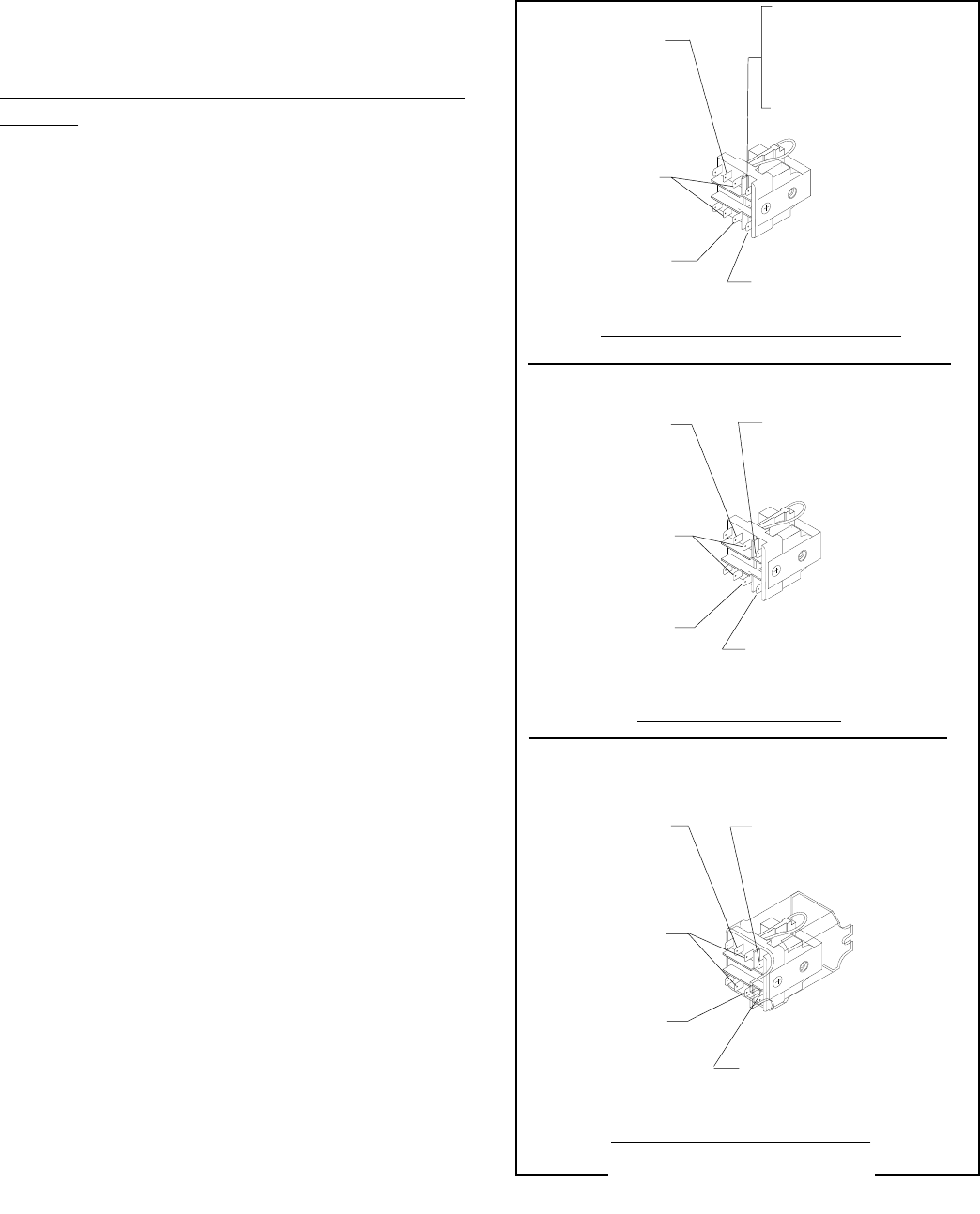
WHI/BLU from
Motor to Relay
K-4
WHI/ORN from Bag
Sensor Switch (A)
WHI/ORN from Bag
Sensor Switch (A)
WHI/BLU from
Motor to Relay
K-4
WHI/RED from
Switch to Relay
K-7 & K-9
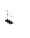
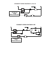
120 VOLT DC MODELS
WHI/VIO from
Switch to Relay
K-6
WHI/ORN from Bag
Sensor Switch (A)
WHI/RED from
Switch to Relay
K-7 & K-9
WHI/BLU from
Motor to Relay
K-4
WHI/VIO from
Switch to Relay
K-6
RED from Main
Harness (B)
230 VOLT AC 50 Hz MODELS
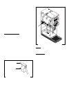
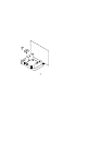
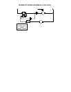
FIG. 15 RELAY TERMINALS
P1707
SERVICE (cont,)
RELAY (cont.)
WHI to Main
Harness 120V (B)
RED/BLK to Main
Harness 240V (B)
WHI/VIO from
Switch to Relay
K-6
WHI/RED from
Switch to Relay
K-7 & K-9
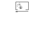
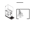
Removal and Replacement (120 Volt and 240V 60 Hz
Models):
1. Remove the wires from the relay terminals.
2. Remove the two #6-32 screws securing the re-
lay bracket w/relay to the grinder base and re-
move bracket and relay as an assembly.
4. Remove the #6-32 screw securing the relay to
the bracket and remove relay and discard.
5. Install new relay to the mounting bracket using
one #6-32 screw,
6. Mount the new relay w/bracket to the grinder base
using two #6-32 screws.
7. Refer Fig. 15 when reconnecting the wires.
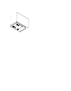
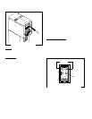
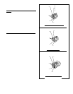
Removal and Replacement (230 volt 50 Hz Models):
1. Remove the wires from the relay terminals.
2. Remove the two #6-32 screws securing the re-
lay to the grinder base.
4. Remove relay and discard.
5. Install new relay to the grinder base using two
#6-32 screw.
6. Refer Fig. 15 when reconnecting the wires.
WHI to Main
Harness (B)
120V AND 240 VOLT AC MODELS
(Revised January 2000)